8 signal transition levels – Texas Instruments Digital Signal Processor SM320F2812-HT User Manual
Page 91
0.4 V (V
OL
)
20%
2.4 V (V
OH
)
80%
0.8 V (V
IL
)
10%
2.0 V (V
IH
)
90%
SGUS062B
–
JUNE 2009
–
REVISED JUNE 2011
6.8
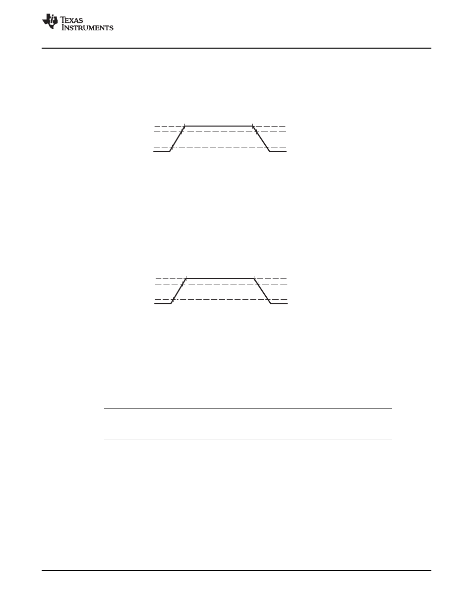
Signal Transition Levels
Note that some of the signals use different reference voltages, see the recommended operating conditions
table. Output levels are driven to a minimum logic-high level of 2.4 V and to a maximum logic-low level of
0.4 V.
shows output levels.
Figure 6-5. Output Levels
Output transition times are specified as follows:
•
For a high-to-low transition, the level at which the output is said to be no longer high is below 80% of
the total voltage range and lower and the level at which the output is said to be low is 20% of the total
voltage range and lower.
•
For a low-to-high transition, the level at which the output is said to be no longer low is 20% of the total
voltage range and higher and the level at which the output is said to be high is 80% of the total voltage
range and higher.
shows the input levels.
Figure 6-6. Input Levels
Input transition times are specified as follows:
•
For a high-to-low transition on an input signal, the level at which the input is said to be no longer high
is 90% of the total voltage range and lower and the level at which the input is said to be low is 10% of
the total voltage range and lower.
•
For a low-to-high transition on an input signal, the level at which the input is said to be no longer low is
10% of the total voltage range and higher and the level at which the input is said to be high is 90% of
the total voltage range and higher.
NOTE
See the individual timing diagrams for levels used for testing timing parameters.
Copyright
©
2009
–
2011, Texas Instruments Incorporated
Electrical Specifications
91
Product Folder Link(s):