Qualstar 501440 Rev. G User Manual
Page 42
5.7
Cabling for TLS-412xxx Libraries with up to twelve AIT-5 Tape
Drives
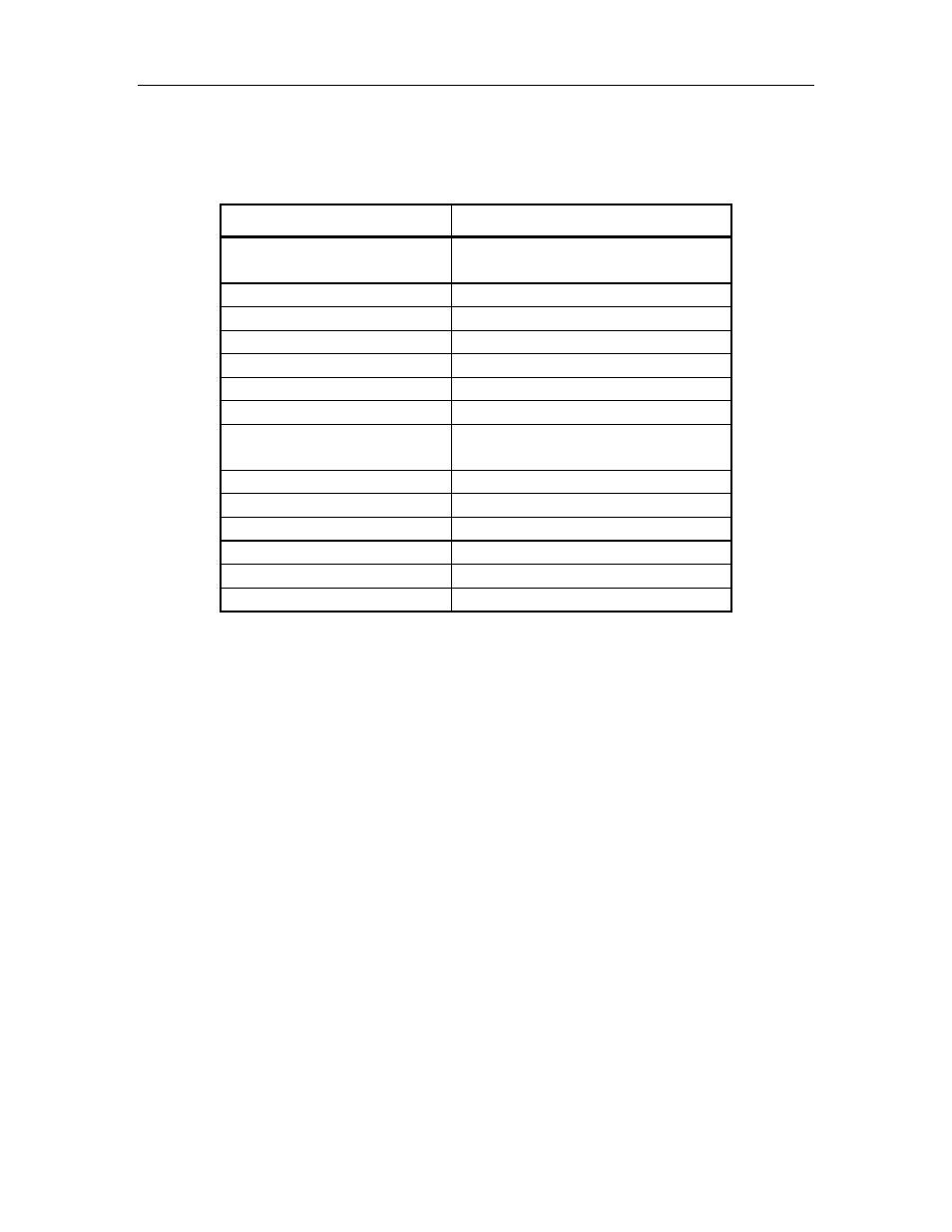
Connectors on Rear of FCO Connectors on Rear of TLS-412xxx
FCO 1 SCSI Channel 0
Left Medium Changer
Left Tape Drive 1 (LT1)
FCO 1 SCSI Channel 1
Left Tape Drive 2 (LT2)
FCO 1 SCSI Channel 2
Left Tape Drive 3 (LT3)
FCO 1 SCSI Channel 3
Left Tape Drive 4 (LT4)
FCO 1 SCSI Channel 4
Left Tape Drive 5 (LT5)
FCO 1 SCSI Channel 5
Left Tape Drive 6 (LT6)
FCO 1Serial
DB9 (Right Executive IV, SERL A)
FCO 2 SCSI Channel 0
Right Medium Changer
Right Tape Drive 1 (RT1)
FCO 2 SCSI Channel 1
Right Tape Drive 2 (RT2)
FCO 2 SCSI Channel 2
Right Tape Drive 3 (RT3)
FCO 2 SCSI Channel 3
Right Tape Drive 4 (RT4)
FCO 2 SCSI Channel 4
Right Tape Drive 5 (RT5)
FCO 2 SCSI Channel 5
Right Tape Drive 6 (RT6)
FCO 2 Serial
DB9 (Left Executive IV, SERL A)
Table 5-6 Preferred Fibre Channel Option Cable Connections for 12 AIT-5 Tape Drives
The following steps outline the actions necessary to connect the cables from two sepa-
rate Fibre Channel Options to the TLS-412xxx with up to twelve AIT-5 tape drives in-
stalled. Please see Figure 5-4 and Figure 5-7. If six or fewer AIT-5 tape drives are
installed see Section 5.6.
1.
Remove power from the TLS: first turn the power switch off and then remove the
power cord.
2.
Remove power from each FCO: first turn the power switch off and then remove
the power cords.
3.
Connect a SCSI Cable from the SCSI Channel 0 connector on FCO 1 to connector
A on the left side on the TLS.
4.
Connect the SCSI Bridge Cable (very short cable) from connector B to C.
5.
Connect a SCSI Cable from the SCSI Channel 1 connector on FCO 1 to connector
E.
6.
Connect a SCSI Cable from the SCSI Channel 2 connector on FCO 1 to connector
G.
7.
Attach an LVD SCSI terminator at connectors D, F and H.
5-10
501440 Rev. J
FCO Type B Installation