Connecting the e1/t1 trunk interfaces, Figure, Electrical earthing – Nortel Networks Mediant TP-1610 SIP User Manual
Page 31: 1 connecting the e1/t1 trunk interfaces
Mediant 2000 SIP User’s Manual
3. Installing the Mediant 2000
Version 4.4
31
July 2005
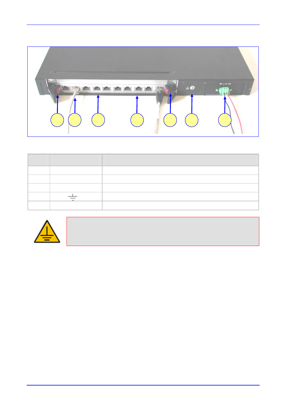
Figure
3-4: Mediant 2000 Rear Panel Cabling (8 Trunks, DC Power))
Table
3-2: Mediant 2000 Rear Panel Cabling (8 Trunks, DC Power) Component Descriptions
Item #
Label
Component Description
1
RTM
latches.
2
ETH
A Category 5 network cable, connected to the Ethernet 1 RJ-45 port.
3
PSTN
8 RJ-48c ports, each supporting a trunk.
4
Protective earthing screw.
5
48V 4A max
2-pin connector for DC.
Electrical Earthing
The unit must be permanently connected to earth via the screw provided at the back on
the unit. Use 14-16 AWG wire and a proper ring terminal for the earthing.
To cable the Mediant 2000, take these 4 steps:
1.
Permanently connect the device to a suitable earth with the protective earthing screw on the
rear connector panel, using 14-16 AWG wire.
2.
Connect the E1/T1 trunk interfaces (refer to Section
below).
3.
Install the Ethernet connection (refer to Section
).
4.
Connect the power supply (refer to Section
on page
).
3.4.1
Connecting the E1/T1 Trunk Interfaces
Connect the Mediant 2000 E1/T1 Trunk Interfaces using either Telco or RJ-48 connectors:
With 50-pin Telco connectors (16-trunk device), take these 3 steps:
1.
Attach the Trunk cable with a 50-pin male Telco connector to the 50-pin female Telco
connector labeled “Trunks 1 8” on the Rear Transition Module (RTM).
2.
Connect the other end of the Trunk cable to the PBX/PSTN switch.
5
2
4
3
1
1
3