Figure 1-17. 802.1q tagging (1 of 4) -35, Figure 1-18. 802.1q tagging (2 of 4) -35, Figure 1-17 – Nortel Networks 450 User Manual
Page 61
BayStack 450 10/100/1000 Series Switches
302401-D Rev 00
1-35
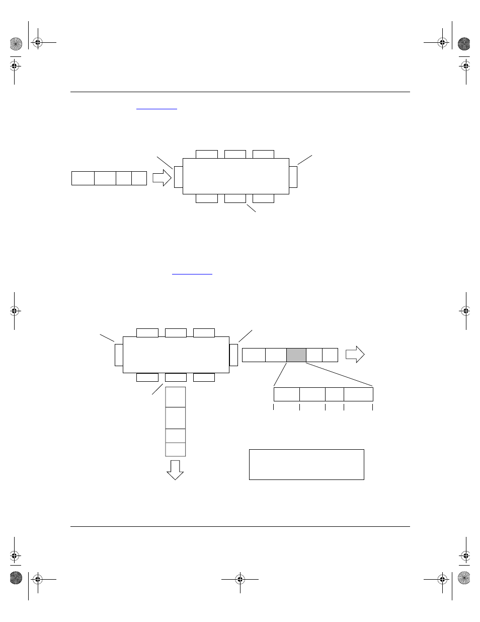
, untagged incoming packets are assigned directly to VLAN 2
(PVID = 2). Port 5 is configured as a tagged member of VLAN 2, and port 7 is
configured as an untagged member of VLAN 2.
Figure 1-17.
802.1Q Tagging (1 of 4)
, the untagged packet is marked (tagged) as it leaves the
switch through port 5, which is configured as a tagged member of VLAN 2. The
untagged packet remains unchanged as it leaves the switch through port 7, which
is configured as an untagged member of VLAN 2.
Figure 1-18.
802.1Q Tagging (2 of 4)
Port 6
DA
SA
Data
CRC
BS45011A
Port 7
Port 8
Port 1
Po
rt
4
Po
rt
5
Port 2
Port 3
802.1Q Switch
PVID = 2
Untagged packet
Untagged member
of VLAN 2
Tagged member
of VLAN 2
Before
BS45012A
Port 6
Port 7
Port 8
Port 1
Po
rt
4
Po
rt
5
Port 2
Port 3
802.1Q Switch
Key
Priority
CFI
VID
- User_priority
- Canonical format indicator
- VLAN identifier
PVID = 2
Tagged member
of VLAN 2
Untagged memeber
of VLAN 2
After
DA
SA
Data
CRC
(*Recalculated)
Outgoing
untagged packet
(unchanged)
DA
SA
Data
CRC*
Tag
VID = 2
Priority
16 bits
3 bits
1 bits
12 bits
8100
CFI
kombk.book Page 35 Tuesday, June 29, 1999 3:25 PM