Figure 1-13. stack down configuration example -29, Figure 1-13 – Nortel Networks 450 User Manual
Page 55
BayStack 450 10/100/1000 Series Switches
302401-D Rev 00
1-29
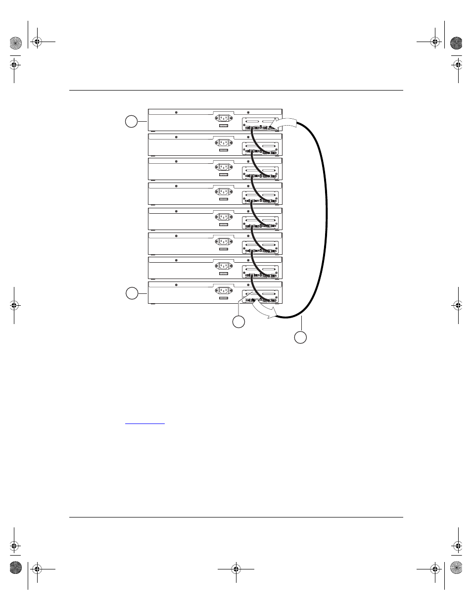
Figure 1-13.
Stack Down Configuration Example
Certain network management station (NMS) applications assume a stack-down
configuration for the graphical user interface (GUI) that represents the stack (see
). For this reason, Nortel Networks recommends that you always
configure the top unit in the stack as the base unit.
In any stack configuration, the following applies:
•
When you apply power to the stack, the base unit initializes and the entire
stack powers up as a single logical unit within 30 seconds.
•
You can attach an RS-232 communications cable to the Console/Comm port
of any switch in the stack.
Unit 2
1 = Base unit
2 = Last unit
3 = Cascade cable (PN 303978-A)
4 = Cascade max-return cable (PN 303979-A)
BS0034B
Unit 1
Unit 4
Unit 3
Unit 6
Unit 5
Unit 8
Unit 7
2
1
In
O
ut
4
3
kombk.book Page 29 Tuesday, June 29, 1999 3:25 PM