Model 3910 – Paradyne 3910 User Manual
Page 17
Chapter Title
1-3
3910-A2-GN32-40
September 1998
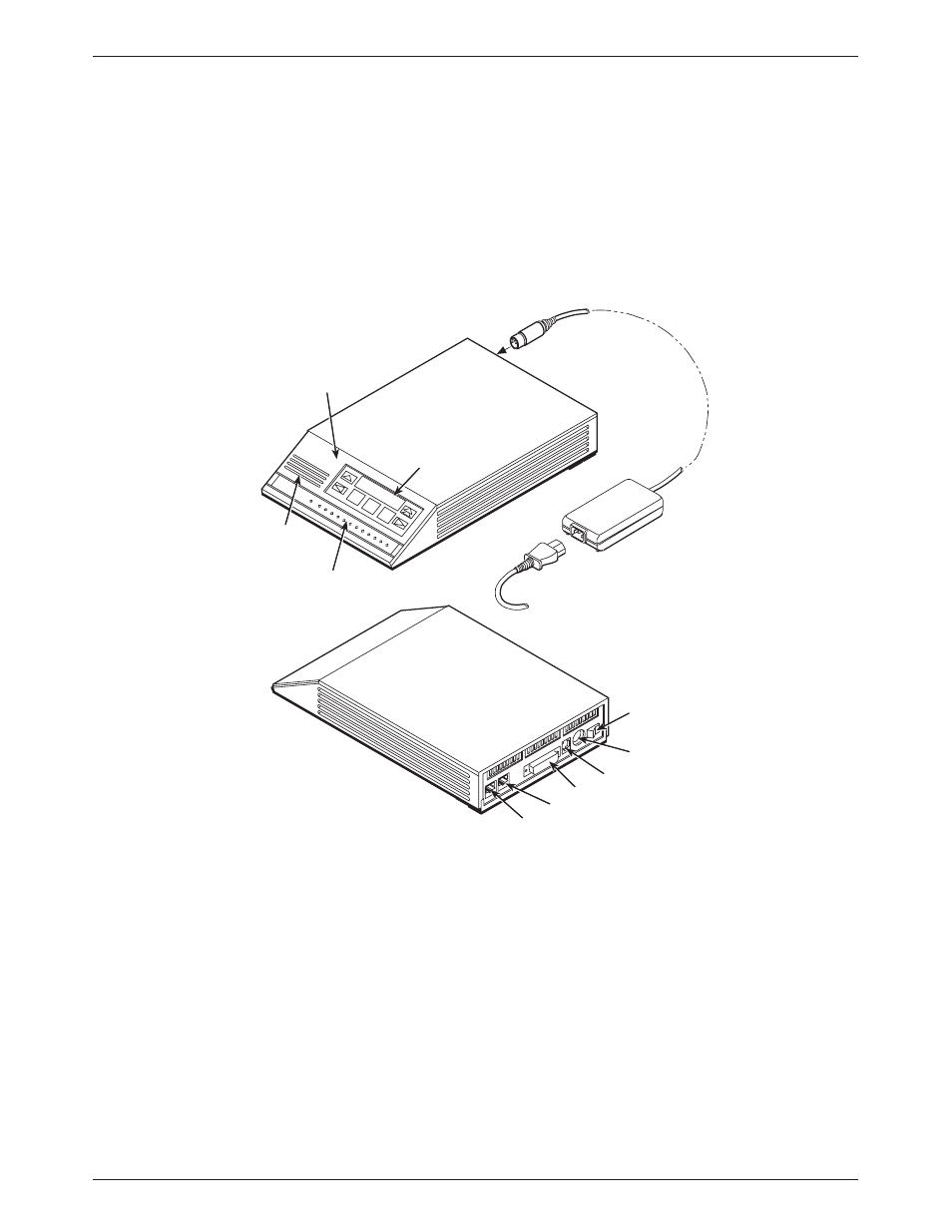
Standalone Model 3910 4-Wire/2-Wire Modem
The standalone Model 3910 modem (Figure 1-1) is capable of either 4-wire/2-wire leased-line or
dial operation. The modem is controlled using either AT commands or the diagnostic control panel
(DCP). The DCP consists of a liquid crystal display (LCD), three function keys, four directional
keys, and a row of 13 LED status indicators. For a better understanding of DCP operation, refer to
Chapter 3, DCP Operation.
SPEAKER
DIAGNOSTIC
CONTROL
PANEL
LCD AND
KEYPAD
STATUS
INDICATORS
POWER
SUPPLY
POWER
CORD
496-14160-03
POWER
ON/OFF
LEASED
DIAL
DTE 1
NMS
POWER IN
Figure 1-1. Model 3910
The rear of the modem contains an ON/OFF power switch, a low voltage dc power connector, an
8-pin modular connector (LEASED) for leased-line connection, an 8-pin modular connector
(DIAL) for dial-line or leased-line backup, a 4-pin modular connector (NMS) for network
management, and a DB-25-S DTE connector.
- ACCULINK 336x E1 (168 pages)
- 6211 (72 pages)
- 6301 (142 pages)
- 3825-A2-GX40-00 (1 page)
- STORMPORT 1020 (2 pages)
- 3911 (280 pages)
- 8314 (136 pages)
- T1 T1 Access Mux 926x (326 pages)
- COMSPHERE 3610 (81 pages)
- 8779 (182 pages)
- COMSPHERE 3616 (135 pages)
- 6212 (102 pages)
- 3830 (125 pages)
- IP DSLAM GranDSLAM 4200 (72 pages)
- ACCULINK 317x E1 (167 pages)
- 6302 (126 pages)
- 7612 SNMP DSU (126 pages)
- and 3165-A4 (316 pages)
- Jetstream CPX-1000 (160 pages)
- IP Broadband Loop Carrier 4000E (20 pages)
- 3164 (296 pages)
- 39xx Series (1 page)
- Hotwire ATM Line Cards 8335 (132 pages)
- 12-Port VoSHDSL Access Multiplexer SAM2000V-12 (10 pages)
- ACCULINK 7800-D1-999 (11 pages)
- COMSPHERE 6700 SERIES (57 pages)
- 3160-A3 (298 pages)
- 1810 (31 pages)
- 12-Port T1 Access Multiplexer TAM1500-12 (8 pages)
- COMSPHERE 3000 (131 pages)
- 8785 (12 pages)
- BitStorm 2600 IP DSLAM (58 pages)
- 3825PLUS (107 pages)
- 6210 (46 pages)
- 4300 (22 pages)
- Fan Tray Assembly 8820-S3-900 (6 pages)
- OpenLane SLM 5.5 (112 pages)
- 8510 RADSL (108 pages)
- Adapter Bracket (1 page)
- 9550 DS3 (20 pages)
- Single T1 Network Access Module (NAM) 9161-A2-GN10-40 (15 pages)
- 5216 (20 pages)
- 9126-II (470 pages)
- COMSPHERE 6700-A2-GB22-00 (60 pages)
- 7915-A1 E1 SDSL (1 page)