Sterling AquaSnap 30RA010-055 User Manual
Page 5
5
T10 — REMOTE SPACE TEMPERATURE SENSOR OR
DUAL LEAVING WATER TEMPERATURE SENSOR —
One of two inputs can be connected to TB5-5 and TB5-6. See
appropriate sensor below.
T10 — Remote Space Temperature Sensor — Sensor T10
(part no. 33ZCT55SPT) is an accessory sensor that is remotely
mounted in the controlled space and used for space tempera-
ture reset. The sensor should be installed as a wall-mounted
thermostat would be (in the conditioned space where it will not
be subjected to either a cooling or heating source or direct
exposure to sunlight, and 4 to 5 ft above the floor).
Space temperature sensor wires are to be connected to
terminals in the unit main control box. The space temperature
sensor includes a terminal block (SEN) and a RJ11 female
connector. The RJ11 connector is used access into the Sterlco
Comfort Network (SCN) at the sensor.
To connect the space temperature sensor (Fig. 9):
1. Using a 20 AWG twisted pair conductor cable rated for
the application, connect 1 wire of the twisted pair to one
SEN terminal and connect the other wire to the other
SEN terminal located under the cover of the space
temperature sensor.
2. Connect the other ends of the wires to terminals 5 and 6
on TB5 located in the unit control box.
Units on the SCN can be monitored from the space at the
sensor through the RJ11 connector, if desired. To wire the RJ11
connector into the SCN (Fig. 10):
1. Cut the SCN wire and strip ends of the red (+), white
(ground), and black (–) conductors. (If another wire color
scheme is used, strip ends of appropriate wires.)
2. Insert and secure the red (+) wire to terminal 5 of the
space temperature sensor terminal block.
3. Insert and secure the white (ground) wire to terminal 4 of
the space temperature sensor.
4. Insert and secure the black (–) wire to terminal 2 of the
space temperature sensor.
5. Connect the other end of the communication bus cable to
the remainder of the SCN communication bus.
T10 — Dual Leaving Water Temperature Sensor — For
dual chiller applications (parallel only are supported), connect
the dual chiller leaving fluid temperature sensor (5 k
Ω ther-
mistor, Sterling part no. HH79NZ029) to the space temperature
input of the Master chiller. If space temperature is required for
reset applications, connect the sensor to the Slave chiller and
configure the slave chiller to broadcast the value to the Master
chiller.
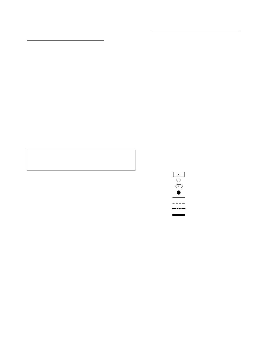
LEGEND FOR FIG. 1-6
IMPORTANT: The cable selected for the RJ11 connector
wiring MUST be identical to the SCN communication bus
wire used for the entire network. Refer to Table 5 for
acceptable wiring.
ALMR
— Alarm Relay
BR
— Boiler Relay
C
— Contactor, Compressor
CB
— Circuit Breaker
CCB
— Compressor Circuit Breaker
CHC
— Cooler/Pump Heater Contactor
COMP
— Compressor
CWFS
— Chilled Water Flow Switch
CWP
— Chilled Water Pump
DPT
— Discharge Pressure Transducer
EMM
— Energy Management
FIOP
— factory Installed Option
FM
— Fan Motor
GND
— Ground
HPS
— High-Pressure Switch
HR
— Heat Relay
ICP
— Inrush Current Protection
IP
— Internal Protection Thermostat
LWT
— Leaving Water Temperature
MBB
— Main Base Board
MLV
— Minimum Load Valve
MS
— Manual Starter
OAT
— Outdoor-Air Thermistor
OL
— Overload
R
— Relay
SPT
— Suction Pressure Transducer
SW
— Switch
T
— Thermistor
TB
— Terminal Block
TNKR
— Storage Tank Heater Relay
TRAN
— Transformer
Terminal Block
Terminal (Unmarked)
Terminal (Marked)
Splice
Factory Wiring
Field Wiring
Accessory or Option Wiring
To indicate common potential only;
not to represent wiring.