Configuring and operating dual chiller con- trol, Fig. 17 — dual chiller thermistor location – Sterling AquaSnap 30RA010-055 User Manual
Page 26
26
As part of a pump maintenance routine, the pumps can be
started to maintain lubrication to the pump seal. To utilize this
function, Cooler Pmp Periodic Start (PM.P.S) [Configuration,
UNIT] must be set to YES. This option is set to NO as the fac-
tory default. If feature is enabled and the pump(s) are not
operating, then the pumps will be operated every other day for
2 seconds starting at 14:00 hours. If a pump has failed and has
an active Alert condition, it will not be started that day.
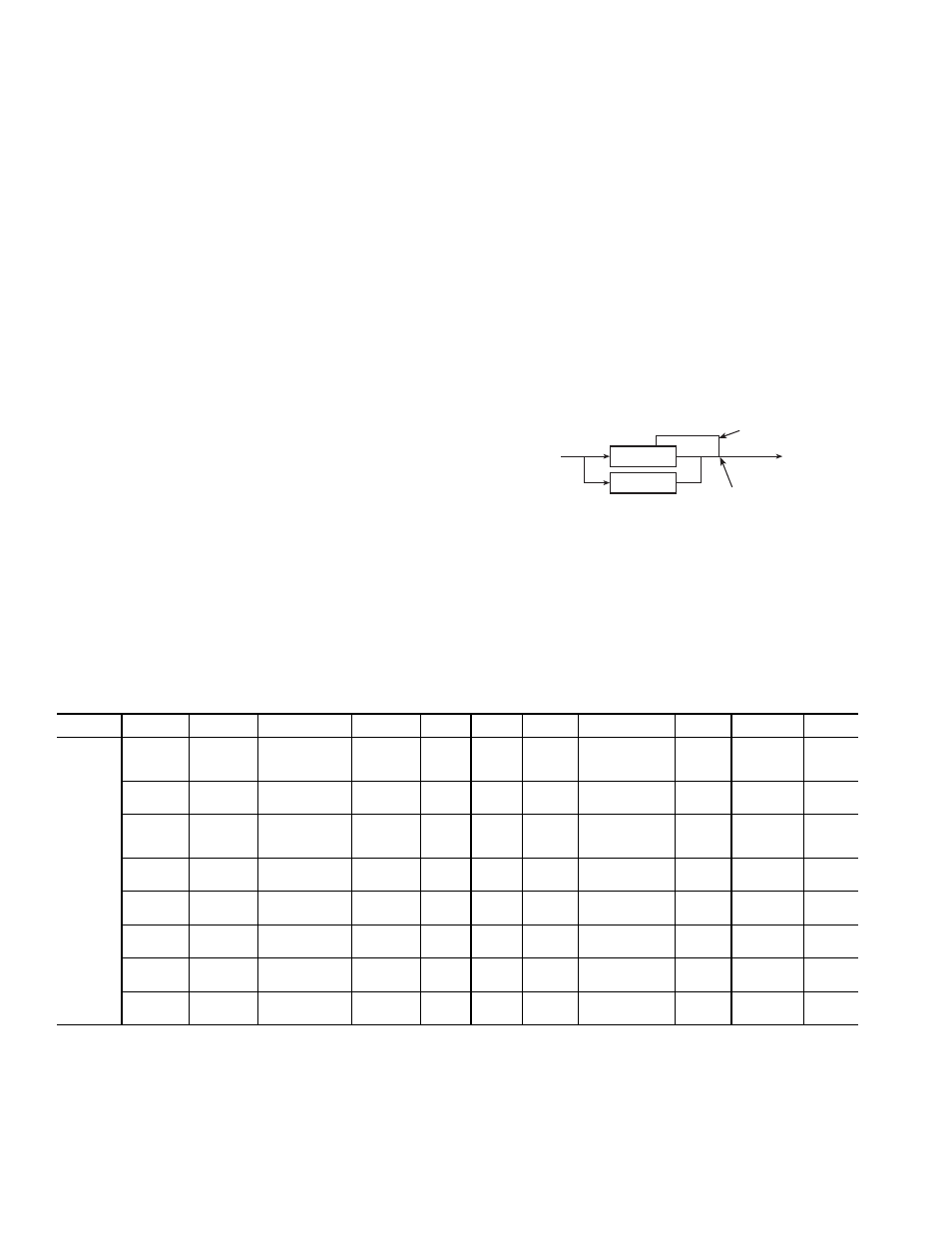
Configuring and Operating Dual Chiller Con-
trol —
The dual chiller routine is available for the control of
two units supplying chilled fluid on a common loop. This
control algorithm is designed for parallel fluid flow arrangement
only. One chiller must be configured as the master chiller, the
other as the slave. An additional leaving fluid temperature
thermistor (Dual Chiller LWT) must be installed as shown in
Fig. 17 and connected to the master chiller. Refer to Sensors sec-
tion, page 4, for wiring. The SCN communication bus must be
connected between the two chillers. Connections can be made
to the SCN screw terminals on TB3. Refer to Sterlco Comfort
Network Interface section, page 3, for wiring information.
Refer to Table 21 for dual chiller configuration. In this
example the master chiller will be configured at address 1 and
the slave chiller at address 2. The master and slave chillers
must reside on the same SCN bus (SCNB) but cannot have the
same SCN address (SCNA) [Configuration, OPT2]. Both
master and slave chillers must have Lead/Lag Chiller Enable
(LLEN) [Configuration, RSET] configured to ENBL. Master/
Slave Select (MSSL) [Configuration, RSET] must be config-
ured to MAST for the master chiller and SLVE for the slave.
Also in this example, the master chiller will be configured to
use Lead/Lag Balance Select (LLBL) and Lead/Lag Balance
Delta (LLBD) [Configuration, RSET] to even out the chiller
run-times weekly. The Lag Start Delay (LLDY) [Configura-
tion, RSET] feature will be set to 10 minutes. This will prevent
the lag chiller from starting until the lead chiller has been at
100% capacity for the length of the delay time. Parallel config-
uration (PARA) [Configuration, RSET] can only be config-
ured to YES. The variables LLBL, LLBD and LLDY are not
used by the slave chiller.
Dual chiller start/stop control is determined by configura-
tion of Control Method (CTRL) [Configuration, OPT2] of the
Master chiller. The Slave chiller should always be configured
for CTRL=0, Switch. If the chillers are to be controlled by
Remote Contacts, both Master and Slave chillers should be
enabled together. Two separate relays or one relay with
two sets of contacts may control the chillers. The Enable/Off/
Remote Contact switch should be in the Remote Contact
position on both the Master and Slave chillers. The Enable/Off/
Remote Contact switch should be in the Enable position for
CTRL=2, Occupancy or CTRL=3, SCN Control.
Both chillers will stop if the Master chiller Enable/Off/
Remote Contact switch is in the Off position. If the Emergency
Stop switch is turned off or an alarm is generated on the Master
chiller the Slave chiller will operate in a Stand-Alone mode.
If the Emergency Stop switch is turned off or an alarm is
generated on the Slave chiller the Master chiller will operate in
a Stand-Alone mode.
The master chiller controls the slave chiller by changing its
Control Mode (STAT) [Run Status, VIEW] and its operating
setpoint or Control Point (CTPT) [Run Status, VIEW].
Table 9 — Marquee Display Menu Structure*
LEGEND
Ckt — Circuit
*Throughout this text, the location of items in the menu structure will be
described in the following format:
Item Expansion (ITEM) [Mode Name, Sub-mode Name]
For example, using the language selection item:
Language Selection (LANG) [Configuration, DISP]
MODE
RUN
STATUS
SERVICE
TEST
TEMPERATURES PRESSURES
SET
POINTS
INPUTS
OUTPUTS
CONFIGURATION
TIME
CLOCK
OPERATING
MODES
ALARMS
SUB-MODE
Auto
Display
(VIEW)
Manual
Mode
On/Off
(TEST)
Unit
Temperatures
(UNIT)
Ckt A
Pressures
(PRC.A)
Cooling
(COOL)
Unit
Discrete
(GEN.I)
Unit
Discrete
(GEN.O)
Display
(DISP)
Unit Time
(TIME)
Modes
(MODE)
Current
(CRNT)
Machine
Hours/Starts
(RUN)
Unit
Outputs
(OUTS)
Ckt A
Temperatures
(CIR.A)
Ckt B
Pressures
(PRC.B)
Head
Pressure
(HEAD)
Ckt A/B
(CRCT)
Ckt A
(CIR.A)
Machine
(UNIT)
Unit Date
(DATE)
Reset
Alarms
(RCRN)
Compressor
Run Hours
(HOUR)
Ckt A Comp
Tests
(CMPA)
Ckt B
Temperatures
(CIR.B)
Brine
Freeze-
point
(FRZ)
Unit
Analog
(4-20)
Ckt B
(CIR.B)
Options 1
(OPT1)
Daylight
Saving
Time
(DST)
Alarm
History
(HIST)
Schedule
Number
(SCH.N)
Compressor
Starts
(STRT)
Ckt B Comp
Tests
(CMPB)
Options 2
(OPT2)
Pump Maint.
(PM)
Temperature
Reset
(RSET)
Local
Schedule
(SCH.L)
Software
Version
(VERS)
Set Point
Select
(SLCT)
Schedule
Override
(OVR)
Service
Configuration
(SERV)
Broadcast
Configuration
(BCST)
MASTER
CHILLER
SLAVE
CHILLER
LEAVING
FLUID
RETURN
FLUID
THERMISTOR
WIRING*
INSTALL DUAL CHILLER LWT
LEAVING FLUID TEMPERATURE
THERMISTOR (T10) HERE
*Depending on piping sizes, use either:
• HH79NZ014 sensor/10HB50106801 well (3-in. sensor/well)
• HH79NZ029 sensor/10HB50106802 well (4-in. sensor/well)
Fig. 17 — Dual Chiller Thermistor Location