Service test (see table 11) – Sterling AquaSnap 30RA010-055 User Manual
Page 23
23
Table 8 — Control Methods and Cooling Set Points
*Dual set point switch input used. CSP1 used when switch input is open. CSP2 used when switch input is closed.
†Cooling set point determined from 4 to 20 mA input to Energy Management Module (EMM) to terminals TB6-3,5.
HEATING
OPERATION — The chiller can be used for
pump outputs or optional factory-installed hydronic system
operation can be utilized for heating applications. The heating
mode is activated when the control sees a field-supplied closed
switch input to terminal block TB5-7,8. The control locks out
cooling when the heat relay input is seen. A field-supplied
boiler relay connection is made using heat relay and alarm
relay contacts. Factory-installed ‘BOILER’ connections exist
in the control panel near TB5 for these applications. Alarms
and alerts A189 through A202 are active during heating
operation.
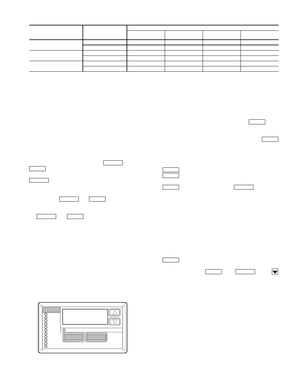
Marquee Display Usage (See Fig. 16 and
Tables 8-27) —
The Marquee display module provides the
user interface to the ComfortLink™ control system. The
display has up and down arrow keys, an
key, and an
key. These keys are used to navigate through the
different levels of the display structure. See Table 9. Press the
key until the display is blank to move through the
top 11 mode levels indicated by LEDs on the left side of the
display.
Pressing the
and
keys simultaneously
will scroll a clear language text description across the display
indicating the full meaning of each display acronym. Pressing
the
and
keys when the display is blank
(Mode LED level) will return the Marquee display to its default
menu of rotating display items. In addition, the password will
be disabled requiring that it be entered again before changes
can be made to password protected items.
Clear language descriptions in English, Spanish, French, or
Portuguese can be displayed when properly configuring the
LANG Item in the Configuration Mode, under the Display
(DISP) submode. See Table 17. Throughout this text, the loca-
tion of items in the menu structure will be described in the fol-
lowing format:
Item Expansion (ITEM) [Mode Name, Sub-mode Name]
For example, using the language selection item:
Language Selection (LANG) [Configuration, DISP]
NOTE: When the LANG variable is changed to 1, 2, or 3, all
appropriate display expansions will immediately change to the
new language. No power-off or control reset is required when
reconfiguring languages.
When a specific item is located, the display will flash show-
ing the operator, the item, followed by the item value and then
followed by the item units (if any). Press the
key to
stop the display at the item value. Items in the Configuration
and Service Test modes are password protected. The display
will flash PASS and WORD when required. Use the
and arrow keys to enter the 4 digits of the password. The
default password is 1111.
Changing item values or testing outputs is accomplished in
the same manner. Locate and display the desired item. Press
to stop the display at the item value. Press the
key again so that the item value flashes. Use the
arrow keys to change the value or state of an item and press the
key to accept it. Press the
key and the
item, value, or units display will resume. Repeat the process as
required for other items.
See Tables 8-27 for further details.
Service Test (See Table 11) —
Both main power
and control circuit power must be on.
The Service Test function should be used to verify proper
operation of condenser fan(s), compressors, minimum load
valve solenoid (if installed), cooler pump(s) and remote alarm
relay. To use the Service Test mode, the Enable/Off/Remote
Contact switch must be in the OFF position. Use the display
keys and Table 11 to enter the mode and display TEST. Press
twice so that OFF flashes. Enter the password if
required. Use either arrow key to change the TEST value to the
ON position and press
. Press
and the
button to enter the OUTS or COMP sub-mode.
Test the condenser fans, cooler pump(s) and alarm relay by
changing the item values from OFF to ON. These discrete
outputs are then turned off if there is no keypad activity for
10 minutes. Test the compressor and minimum load valve
solenoid (if installed) outputs in a similar manner. The
minimum load valve solenoids will be turned off if there is no
keypad activity for 10 minutes. Compressors will stay on until
they are turned off by the operator. The Service Test mode will
remain enabled for as long as there is one or more compressors
running. All safeties are monitored during this test and will turn
a compressor, circuit or the machine off if required. Any other
mode or sub-mode can be accessed, viewed, or changed during
the TEST mode. The STAT item [Run/Status, VIEW] will dis-
play “0” as long as the Service mode is enabled. The TEST
sub-mode value must be changed back to OFF before the chill-
er can be switched to Enable or Remote contact for normal
operation.
CONTROL
TYPE
(CTRL)
OCCUPANCY
STATE
COOLING SET POINT SELECT (CLSP)
0
(single)
1
(dual, switch)
2
(dual, occ)
3
(4 to 20 mA)
0 (switch)
Occupied
ON,CSP1
ON*
ON,CSP1
ON†
Unoccupied
ON,CSP1
ON*
ON,CSP2
ON
2 (Occupancy)
Occupied
ON,CSP1
ON*
Illegal
ON†
Unoccupied
OFF
OFF
Illegal
OFF
3 (
SCN)
Occupied ON,CSP1 ON* ON,CSP1 ON†
Unoccupied
ON,CSP1
ON*
ON,CSP2
ON†
ESCAPE
ENTER
ESCAPE
ESCAPE
ENTER
ESCAPE
ENTER
ENTER
ENTER
ENTER
ENTER
ENTER
ESCAPE
ENTER
ENTER
ESCAPE
Run Status
Service Test
Temperature
Pressures
Setpoints
Inputs
Outputs
Configuration
Time Clock
Operating Modes
Alarms
Alarm Status
ENTER
MODE
ESCAPE
Fig. 16 — Scrolling Marquee Display