Floppy connector, Ipmi, Uper x6dh3-g2 – SUPER MICRO Computer X6DHi-G2 User Manual
Page 50
2-30
X6DH3-G2/X6DHi-G2 User's Manual
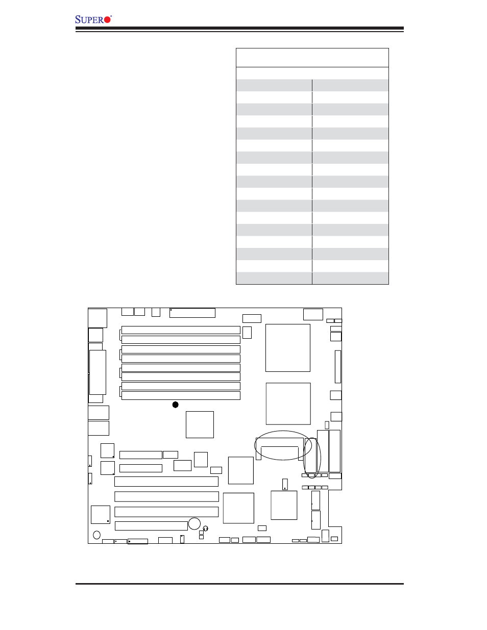
Floppy Connector
The fl oppy connector is located
between the IDE connectors and
the IPMI socket. See the table
below for pin defi nitions.
Floppy
LAN1
®
JLAN1
S
UPER X6DH3-G2
LAN2
DIMM 2A
DIMM 2B
DIMM 3A
DIMM 3B
DIMM 4A
DIMM 4B
DIMM 1B
DIMM 1A
12V 8-pin
PWR
JF
1
FP
Control
JOH
IPMI
IDE2
Flo
ppy
BIOS
Fan4
S
MB
PCI-X100 MHz
PCI-X 100 MHz ZCR (Green Slot)
PCI-X 133 MHz
Battery
JPL1
PCI-E X8
VGA
COM1
USB
0/1
KB/MS
Fan6 Fan5
ATX PWR
12V 4-Pin
PWR
Parrallel
Port
24-Pin
Fan
7
JPW1
Fan8
CPU1
S I/O
PSF
Fan3
IDE1
PCI-33 MHz
USB2/3
ICH
JPG1
JWD
Slot1
Slot2
Slot3
Slot4
Slot5
Slot6
PCI-E X8
GLAN
CTRL
6300ESB
Buzzer
PXH
JBT1
I-SATA1
GLAN
CTRL
JPL2
JL1
JP
S1
SAS
CTRL
Fan2
Fan1
JAR
J3P
CPU2
E7520
Bank1
Bank2
Bank3
Bank4
WOL
SEPC
COM2
SMB PS
JWOR
JS10
VGA
CTRL
JD1
JI
2
C2
I-SATA0
DS5 DS6 DS7 DS8
DS1 DS2 DS3 DS4
SAS4-7
SAS0-3
JSM1
JS9
JP9
J1D1
J32
J38
J33
J14
J7
JLAN1
JLAN2
JI
2
C1
J31
JSM2
JP1
IPMI
There is an IPMI 2.0 Socket on
the motherboard. Refer to the
layout below for the IPMI Socket
location.
IPMI
Floppy Drive Connector
Pin Defi nitions (Floppy)
Pin# Defi nition Pin # Defi nition
1
Ground
2
FDHDIN
3
Ground
4
Reserved
5
Key
6
FDEDIN
7
Ground
8
Index
9
Ground
10
Motor Enable
11
Ground
12
Drive Select B
13
Ground
14
Drive Select B
15
Ground
16
Motor Enable
17
Ground
18
DIR
19
Ground
20
STEP
21
Ground
22
Write Data
23
Ground
24
Write Gate
25
Ground
26
Track 00
27
Ground
28
Write Protect
29
Ground
30
Read Data
31
Ground
32
Side 1 Select
33
Ground
34
Diskette