Serial ports, Chassis intrusion, Uper x6dh3-g2 – SUPER MICRO Computer X6DHi-G2 User Manual
Page 34
2-14
X6DH3-G2/X6DHi-G2 User's Manual
LAN1
®
JLAN
1
S
UPER X6DH3-G2
LAN2
DIMM 2A
DIMM 2B
DIMM 3A
DIMM 3B
DIMM 4A
DIMM 4B
DIMM 1B
DIMM 1A
12V 8-pin
PWR
JF
1
FP
Control
JOH
IPMI
ID
E
2
Flo
ppy
BIOS
Fan4
SMB
PCI-X100 MHz
PCI-X 100 MHz ZCR (Green Slot)
PCI-X 133 MHz
Battery
JPL1
PCI-E X8
VGA
COM1
USB
0/1
KB/MS
Fan6 Fan5
ATX PWR
12V 4-Pin
PWR
Parrallel
Port
24-Pin
F
a
n
7
JPW1
Fan8
CPU1
S I/O
PSF
Fan3
ID
E
1
PCI-33 MHz
USB2/3
ICH
JPG1
JWD
Slot1
Slot2
Slot3
Slot4
Slot5
Slot6
PCI-E X8
GLAN
CTRL
6300ESB
Buzzer
PXH
JBT1
I-SATA1
GLAN
CTRL
JPL2
JL1
JP
S
1
SAS
CTRL
Fan2
Fan1
JAR
J3P
CPU2
E7520
Bank1
Bank2
Bank3
Bank4
WOL
SEPC
COM2
SMB PS
JWOR
JS10
VGA
CTRL
JD1
JI
2
C2
I-SATA0
DS5 DS6 DS7 DS8
DS1 DS2 DS3 DS4
SAS4-7
SAS0-3
JSM1
JS9
JP9
J1D1
J32
J38
J33
J14
J7
JLAN1
JLAN2
JI
2
C1
J31
JSM2
JP1
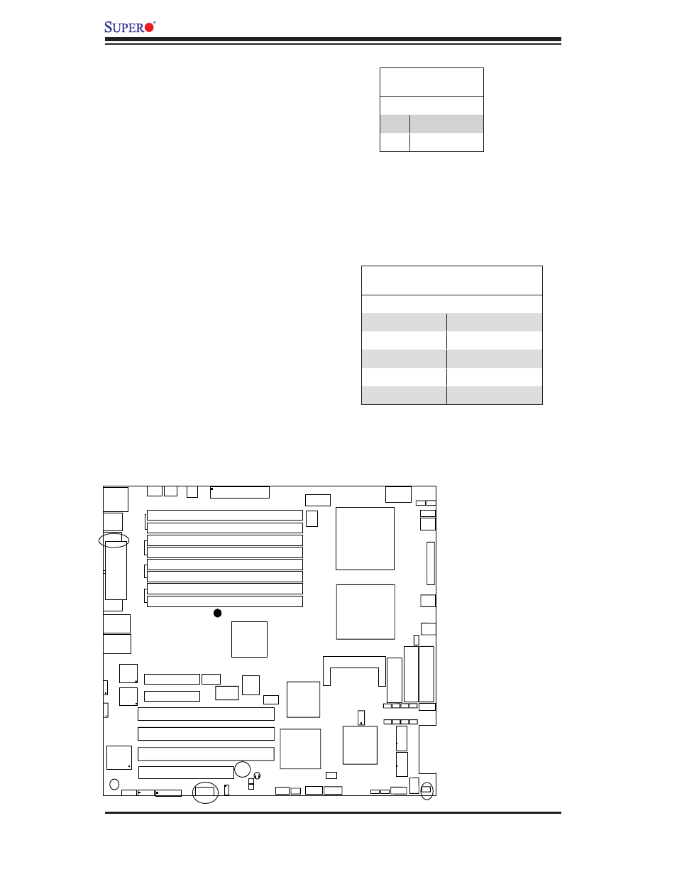
Serial Ports
The COM1 serial port is located under
the parallel port and COM2 is located
below the PCI Slot1 (see the Mother-
board layout on Page 1-4). See the
table on the right for pin defi nitions.
Chassis Intrusion
A Chassis Intrusion header is located
at JL1. Attach the appropriate cable to
inform you of a chassis intrusion.
C h a s s i s
Intrusion
COM2
COM1
Chassis Intrusion
Pin Defi nitions (JL1)
Pin# Defi nition
1
Intrusion Input
2
Ground
Serial Port Pin Defi nitions
(COM1/COM2)
Pin # Defi nition
Pin # Defi nition
1
CD
6
DSR
2
RD
7
RTS
3
TD
8
CTS
4
DTR
9
RI
5
Ground
10
NC
Note: Pin 10 is included on the header but not on
the port. NC indicates no connection.