Power smb (i, C) connector, Chapter 2: installation – SUPER MICRO Computer X6DHi-G2 User Manual
Page 39: Uper x6dh3-g2
Chapter 2: Installation
2-19
LAN1
®
JLAN
1
S
UPER X6DH3-G2
LAN2
DIMM 2A
DIMM 2B
DIMM 3A
DIMM 3B
DIMM 4A
DIMM 4B
DIMM 1B
DIMM 1A
12V 8-pin
PWR
JF1
FP
Control
JOH
IPMI
IDE2
Floppy
BIOS
Fan4
SMB
PCI-X100 MHz
PCI-X 100 MHz ZCR (Green Slot)
PCI-X 133 MHz
Battery
JPL1
PCI-E X8
VGA
COM1
USB
0/1
KB/MS
Fan6 Fan5
ATX PWR
12V 4-Pin
PWR
Parrallel
Port
24-Pin
Fa
n
7
JPW1
Fan8
CPU1
S I/O
PSF
Fan3
IDE1
PCI-33 MHz
USB2/3
ICH
JPG1
JWD
Slot1
Slot2
Slot3
Slot4
Slot5
Slot6
PCI-E X8
GLAN
CTRL
6300ESB
Buzzer
PXH
JBT1
I-SATA1
GLAN
CTRL
JPL2
JL1
JP
S
1
SAS
CTRL
Fan2
Fan1
JAR
J3P
CPU2
E7520
B
ank1
B
an
k
2
B
an
k
3
Ba
nk4
WOL
SEPC
COM2
SMB PS
JWOR
JS10
VGA
CTRL
JD1
JI
2
C2
I-SATA0
DS5 DS6 DS7 DS8
DS1 DS2 DS3 DS4
SAS4-7
SAS0-3
JSM1
JS9
JP9
J1D1
J32
J38
J33
J14
J7
JLAN1
JLAN2
JI
2
C1
J31
JSM2
JP1
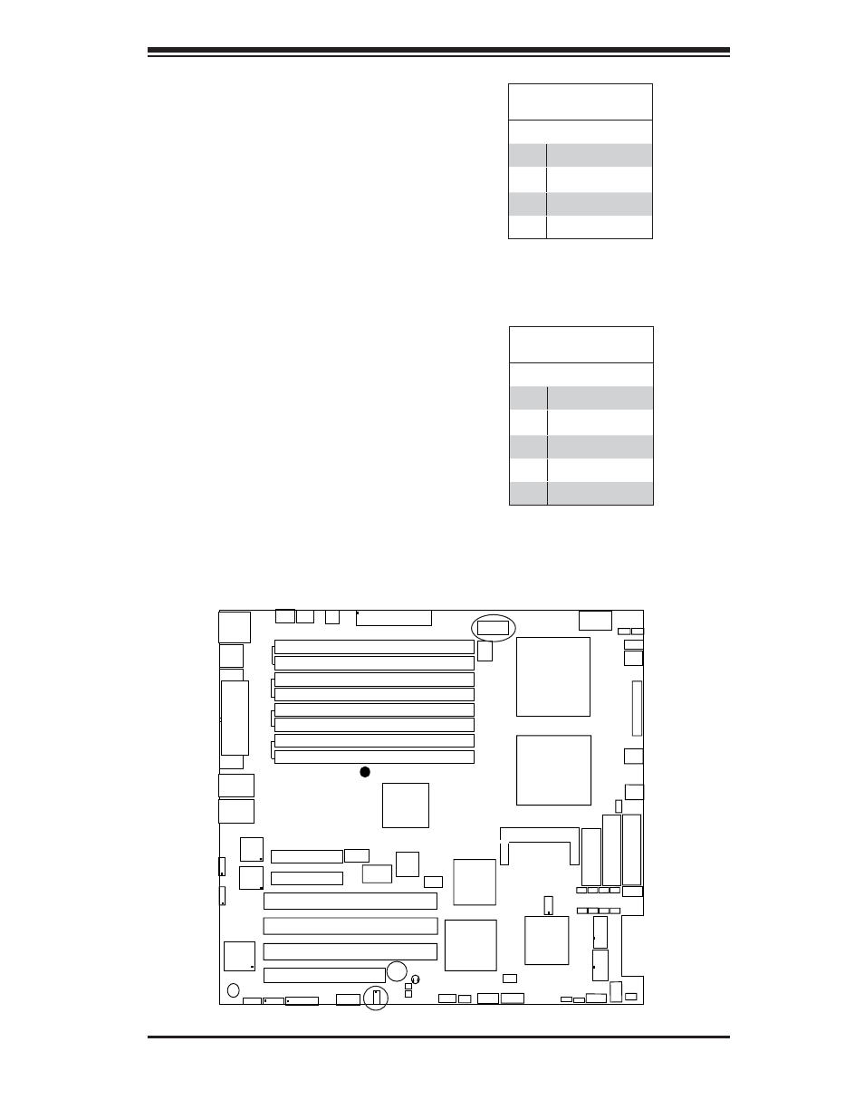
SMB
A System Management Bus header
i s l o c a t e d a t J 11 . C o n n e c t t h e
appropriate cable here to utilize SMB
on your system. See the table on the
right for pin defi nitions.
Power SMB (I
2
C) Connector
Power SMB (I
2
C) Connector (J32),
located between the 8-pin PWR
Connector and the 24-pin PWR Con-
nector, monitors the status of PWR
Supply, Fan and system temperature.
See the table on the right for pin
defi nitions.
SMB
PWR SMB
PWR SMB
Pin Defi nitions
Pin# Defi nition
1
Clock
2
Data
3
PWR Fail
4
Ground
5
+3.3V
SMB Header
Pin Defi nitions
Pin# Defi nition
1
Data
2
Ground
3
Clock
4
No Connection