Universal serial bus (usb), Chapter 2: installation, Uper x6dh3-g2 – SUPER MICRO Computer X6DHi-G2 User Manual
Page 35
Chapter 2: Installation
2-15
LAN1
®
JLAN
1
S
UPER X6DH3-G2
LAN2
DIMM 2A
DIMM 2B
DIMM 3A
DIMM 3B
DIMM 4A
DIMM 4B
DIMM 1B
DIMM 1A
12V 8-pin
PWR
JF1
FP
Control
JOH
IPMI
IDE2
Flo
ppy
BIOS
Fan4
SMB
PCI-X100 MHz
PCI-X 100 MHz ZCR (Green Slot)
PCI-X 133 MHz
Battery
JPL1
PCI-E X8
VGA
COM1
USB
0/1
KB/MS
Fan6 Fan5
ATX PWR
12V 4-Pin
PWR
Parrallel
Port
24-Pin
Fan
7
JPW1
Fan8
CPU1
S I/O
PSF
Fan3
IDE1
PCI-33 MHz
USB2/3
ICH
JPG1
JWD
Slot1
Slot2
Slot3
Slot4
Slot5
Slot6
PCI-E X8
GLAN
CTRL
6300ESB
Buzzer
PXH
JBT1
I-SATA1
GLAN
CTRL
JPL2
JL1
JP
S
1
SAS
CTRL
Fan2
Fan1
JAR
J3P
CPU2
E7520
Bank1
Bank2
Bank3
Bank4
WOL
SEPC
COM2
SMB PS
JWOR
JS10
VGA
CTRL
JD1
JI
2
C2
I-SATA0
DS5 DS6 DS7 DS8
DS1 DS2 DS3 DS4
SAS4-7
SAS0-3
JSM1
JS9
JP9
J1D1
J32
J38
J33
J14
J7
JLAN1
JLAN2
JI
2
C1
J31
JSM2
JP1
USB 0/1
FP USB 2/3
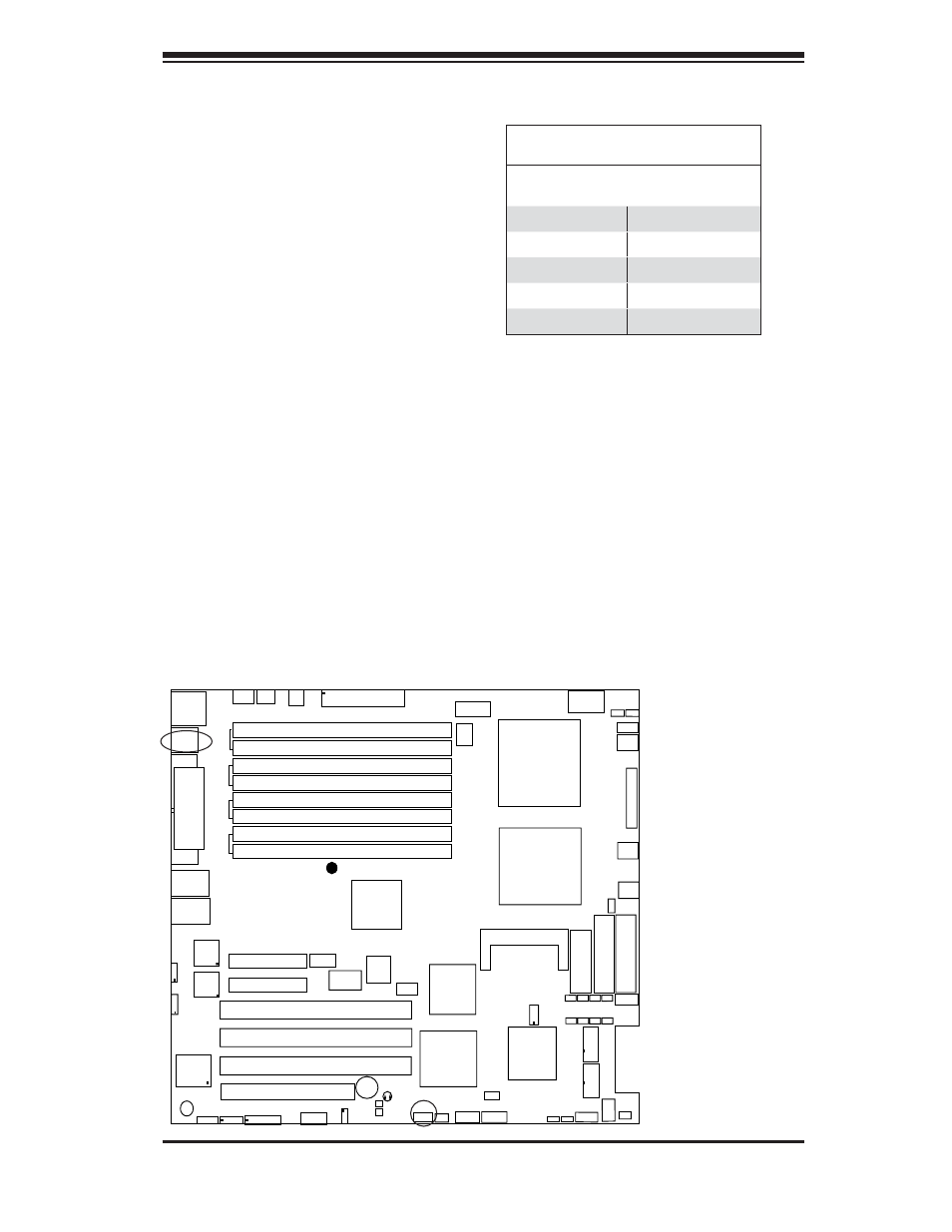
Universal Serial Bus (USB)
There are two Universal Serial Bus
ports (USB 0/1) located on the I/O
back panel and additional two USB
USB (2/3) located near the 6300
ESB chip (South Bridge) on the
motherboard. These ports (FP USB2
and USB3) can be used to provide
front side chassis access (cables not
included). See the tables on the right
for pin defi nitions.
Universal Serial Bus
Pin Defi nitions
USB 0/1
Pin # Defi nition
(FP) USB 2/3
Pin # Defi nition
1
+5V
1
+5V
2
PO-
2
PO-
3
PO+
3
PO+
4
Ground
4
Ground
5
N/A
5
Key