Parallel (printer) port connector, Chapter 2: installation – SUPER MICRO Computer X6DHi-G2 User Manual
Page 49
Chapter 2: Installation
2-29
LAN1
®
JLAN1
S
UPER X6DH3-G2
LAN2
DIMM 2A
DIMM 2B
DIMM 3A
DIMM 3B
DIMM 4A
DIMM 4B
DIMM 1B
DIMM 1A
12V 8-pin
PWR
JF1
FP
Control
JOH
IPMI
IDE
2
Floppy
BIOS
Fan4
SMB
PCI-X100 MHz
PCI-X 100 MHz ZCR (Green Slot)
PCI-X 133 MHz
Battery
JPL1
PCI-E X8
VGA
COM1
USB
0/1
KB/MS
Fan6 Fan5
ATX PWR
12V 4-Pin
PWR
Parrallel
Port
24-Pin
F
an7
JPW1
Fan8
CPU1
S I/O
PSF
Fan3
IDE1
PCI-33 MHz
USB2/3
ICH
JPG1
JWD
Slot1
Slot2
Slot3
Slot4
Slot5
Slot6
PCI-E X8
GLAN
CTRL
6300ESB
Buzzer
PXH
JBT1
I-SATA1
GLAN
CTRL
JPL2
JL1
JPS1
SAS
CTRL
Fan2
Fan1
JAR
J3P
CPU2
E7520
Bank1
Bank2
Bank3
Bank4
WOL
SEPC
COM2
SMB PS
JWOR
JS10
VGA
CTRL
JD1
JI
2
C2
I-SATA0
DS5 DS6 DS7 DS8
DS1 DS2 DS3 DS4
SAS4-7
SAS0-3
JSM1
JS9
JP9
J1D1
J32
J38
J33
J14
J7
JLAN1
JLAN2
JI
2
C1
J31
JSM2
JP1
2-8
Parallel Port, Floppy, Hard Disk Drive and IPMI
Connections
Note the following when connecting the fl oppy and hard disk drive cables:
• The fl oppy disk drive cable has seven twisted wires.
• A red mark on a wire typically designates the location of pin 1.
• A single fl oppy disk drive ribbon cable has 34 wires and two connectors to provide
for two fl oppy disk drives. The connector with twisted wires always connects to
drive A, and the connector that does not have twisted wires always connects to
drive B.
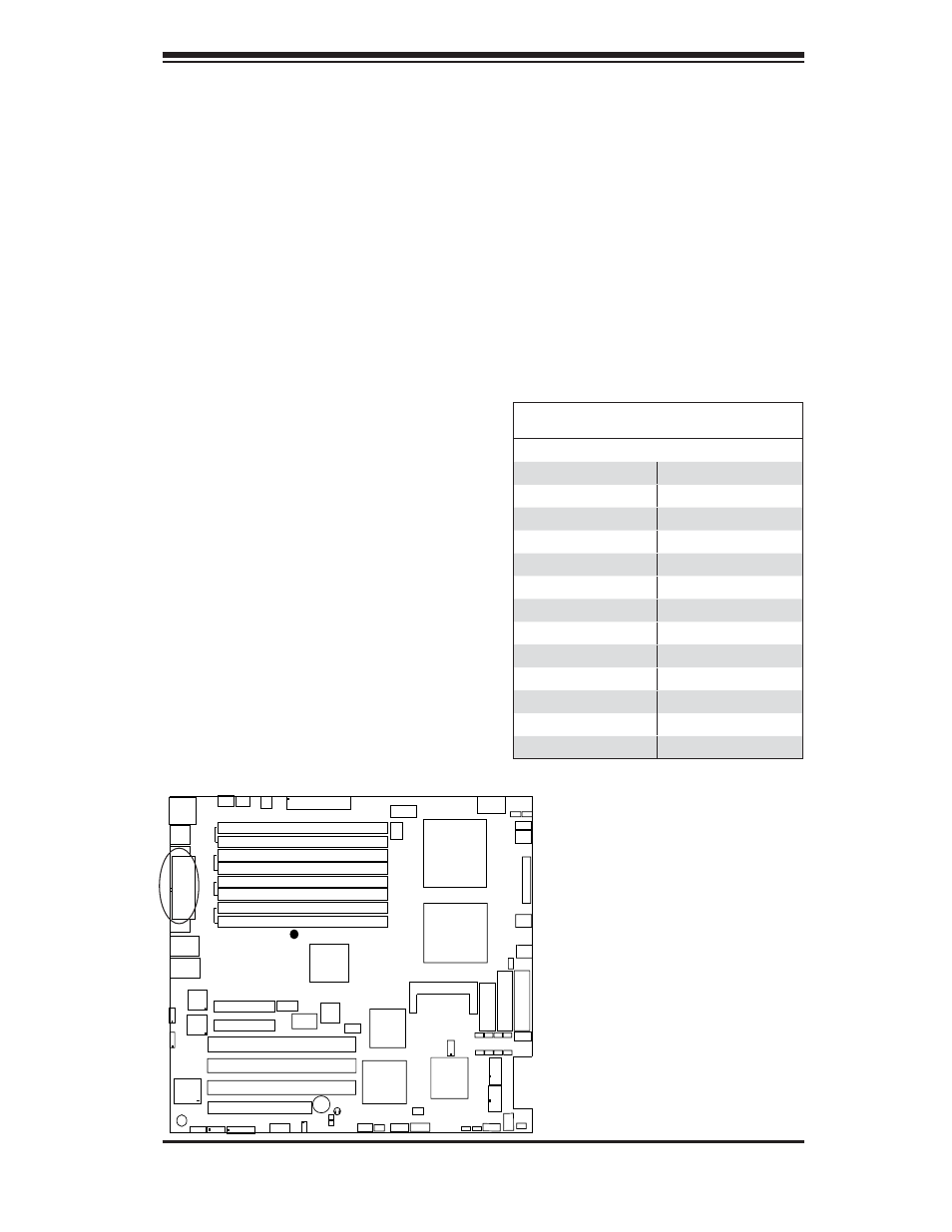
Parallel (Printer) Port
Connector
The parallel (printer) port is located
above the COM1/VGA Connectors.
See the table on the right for pin
defi nitions.
Parallel
Port
Parallel (Printer) Port Connector
Pin Defi nitions (J11)
Pin# Defi nition Pin # Defi nition
1
Strobe-
2
Auto Feed-
3
Data Bit 0
4
Error-
5
Data Bit 1
6
Init-
7
Data Bit 2
8
SLCT IN-
9
Data Bit 3
10
GND
11
Data Bit 4
12
GND
13
Data Bit 5
14
GND
15
Data Bit 6
16
GND
17
Data Bit 7
18
GND
19
ACK
20
GND
21
BUSY
22
Write Data
23
PE
24
Write Gate
25
SLCT
26
NC