Overheat/fanfail led, Power fail led, Power button oh/fan fail led – SUPER MICRO Computer X6DHi-G2 User Manual
Page 32: Nic1 led reset button, Power fail led hdd led power led, Nic2 led
2-12
X6DH3-G2/X6DHi-G2 User's Manual
Power Button
OH/Fan Fail LED
1
NIC1 LED
Reset Button
2
Power Fail LED
HDD LED
Power LED
Reset
Pwr
Vcc
Vcc
Vcc
Vcc
Ground
Ground
19
20
Vcc
X
Ground
NMI
X
Vcc
NIC2 LED
Overheat/FanFail LED
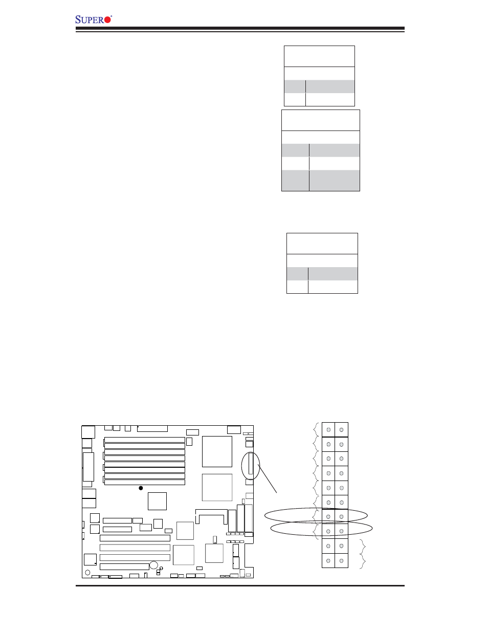
Connect an LED to the OH/Fan Fail
connection on pins 7 and 8 of JF1 to
provide advanced warnings of chas-
sis overheating or system fan failure.
Refer to the table on the right for pin
defi nitions.
LAN1
®
JLAN
1
S
UPER X6DH3-G2
LAN2
DIMM 2A
DIMM 2B
DIMM 3A
DIMM 3B
DIMM 4A
DIMM 4B
DIMM 1B
DIMM 1A
12V 8-pin
PWR
JF
1
FP
Control
JOH
IPMI
IDE2
Flo
pp
y
BIOS
Fan4
S
MB
PCI-X100 MHz
PCI-X 100 MHz ZCR (Green Slot)
PCI-X 133 MHz
Battery
JPL1
PCI-E X8
VGA
COM1
USB
0/1
KB/MS
Fan6 Fan5
ATX PWR
12V 4-Pin
PWR
Parrallel
Port
24-Pin
F
an
7
JPW1
Fan8
CPU1
S I/O
PSF
Fan3
ID
E1
PCI-33 MHz
USB2/3
ICH
JPG1
JWD
Slot1
Slot2
Slot3
Slot4
Slot5
Slot6
PCI-E X8
GLAN
CTRL
6300ESB
Buzzer
PXH
JBT1
I-SATA1
GLAN
CTRL
JPL2
JL1
JPS
1
SAS
CTRL
Fan2
Fan1
JAR
J3P
CPU2
E7520
Bank1
Bank2
Bank3
Bank4
WOL
SEPC
COM2
SMB PS
JWOR
JS10
VGA
CTRL
JD1
JI
2
C2
I-SATA0
DS5 DS6 DS7 DS8
DS1 DS2 DS3 DS4
SAS4-7
SAS0-3
JSM1
JS9
JP9
J1D1
J32
J38
J33
J14
J7
JLAN1
JLAN2
JI
2
C1
J31
JSM2
JP1
OH/Fan Fail LED
Pin Defi nitions (JF1)
Pin# Defi nition
7
Vcc
8
Ground
OH/Fan Fail Indicator
Status
State Defi nition
Off
Normal
On
Overheat
Flash-
ing
Fan Fail
OH/Fan Fail LED
PWR Fail LED
Power Fail LED
The Power Fail LED is located on Pins
5 and 6 of JF1. Refer to the table on
the right for pin defi nitions.
PWR Fail LED
Pin Defi nitions (JF1)
Pin# Defi nition
5
Vcc
6
Ground