Adaptec sas smb power (i, C) connector (*for the x6dh3-g2 only), Adaptec sas – SUPER MICRO Computer X6DHi-G2 User Manual
Page 40: Uper x6dh3-g2
2-20
X6DH3-G2/X6DHi-G2 User's Manual
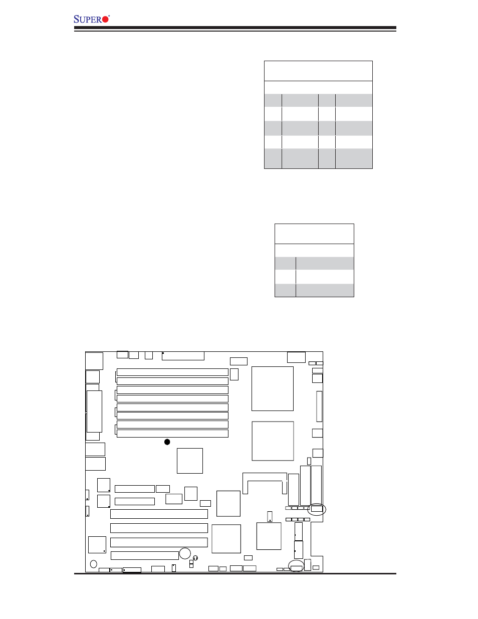
Adaptec SAS Activity
Output LED Header (*For
the X6DH3-G2 only)
Adaptec SAS Activity Output LED
Header (JS9), located next to IDE1,
displays the status of Adaptec's SAS
Activities. See the table on the right for
pin defi nitions. (*Note: SAS Common
LED will be activated when any of
SAS0 to SAS7 LEDs is activated.)
SAS Act. LED
LAN1
®
JLAN1
S
UPER X6DH3-G2
LAN2
DIMM 2A
DIMM 2B
DIMM 3A
DIMM 3B
DIMM 4A
DIMM 4B
DIMM 1B
DIMM 1A
12V 8-pin
PWR
JF
1
FP
Control
JOH
IPMI
IDE2
Flo
ppy
BIOS
Fan4
S
MB
PCI-X100 MHz
PCI-X 100 MHz ZCR (Green Slot)
PCI-X 133 MHz
Battery
JPL1
PCI-E X8
VGA
COM1
USB
0/1
KB/MS
Fan6 Fan5
ATX PWR
12V 4-Pin
PWR
Parrallel
Port
24-Pin
Fan
7
JPW1
Fan8
CPU1
S I/O
PSF
Fan3
IDE1
PCI-33 MHz
USB2/3
ICH
JPG1
JWD
Slot1
Slot2
Slot3
Slot4
Slot5
Slot6
PCI-E X8
GLAN
CTRL
6300ESB
Buzzer
PXH
JBT1
I-SATA1
GLAN
CTRL
JPL2
JL1
JP
S
1
SAS
CTRL
Fan2
Fan1
JAR
J3P
CPU2
E7520
Bank1
Bank2
Bank3
Bank4
WOL
SEPC
COM2
SMB PS
JWOR
JS10
VGA
CTRL
JD1
JI
2
C2
I-SATA0
DS5 DS6 DS7 DS8
DS1 DS2 DS3 DS4
SAS4-7
SAS0-3
JSM1
JS9
JP9
J1D1
J32
J38
J33
J14
J7
JLAN1
JLAN2
JI
2
C1
J31
JSM2
JP1
Adaptec SAS SMB Power
(I
2
C) Connector (*For the
X6DH3-G2 only)
Adaptec SAS
I
2
C Connector (JS10),
located between SAS Slot#7 and
Fan4, monitors the status of Power
Supply System Management Bus for
Adaptec's SAS ports. See the table
on the right for pin defi nitions.
SAS PWR SMB
SAS_ACT_Output
Pin Defi nitions
Pin# Defi nition Pin# Defi nition
1
SAS0:Act
6
SAS4:Act
2
SAS1:Act
7
SAS5:Act
3
SAS2:Act
8
SAS6:Act
4
SAS3:Act
9
SAS7:Act
5
*SAS
Common
10
NC
SAS SMB PWR
Pin Defi nitions
Pin# Defi nition
1
TWSI_SDA
2
Ground
3
TWSI_SCK