An93 – Silicon Laboratories SI2493/57/34/15/04 User Manual
Page 291
AN93
Rev. 1.3
291
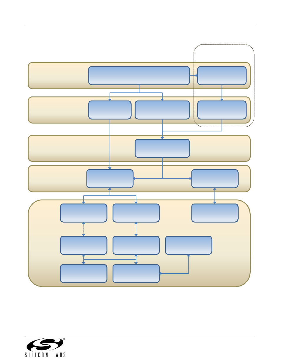
Figure 75 illustrates the MCU software architecture, and the MCU and modem hardware connections.
Figure 75. MCU Software and Modem Interface
MCU
Modem
Interrupt service and/or polling
Hardware access layer
Buffer management layer
Application layer
(Optional)
Dot‐command shell
dot_command_loop.c
modem_main.c
application_buffers.c
status_control.c
ISR_and_polling.c
test_code.c
modem_hardware.c
Parallel interface
MCU_hardware.c
MCU hardware
(UART, timers, etc.)
SPI master
Parallel interface
SPI slave
UART interface
Hardware Interface
Register 1 (HIR1)
Transmit and
receive FIFOs
This manual is related to the following products: