Speakerphone configuration, An93 – Silicon Laboratories SI2493/57/34/15/04 User Manual
Page 219
AN93
Rev. 1.3
219
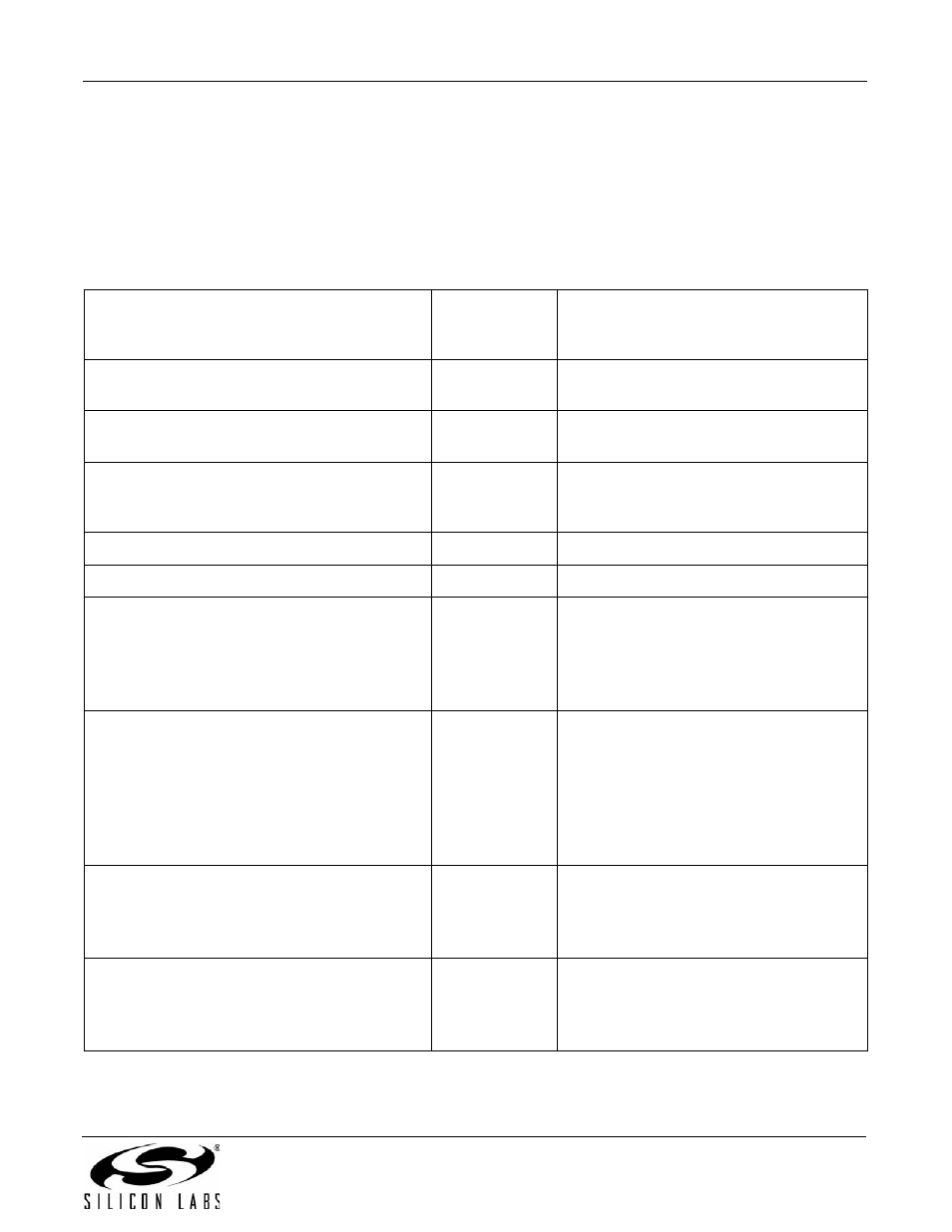
7.7.4. Speakerphone Configuration
This section covers the speakerphone call and answer cases, and the switching between the handset mode and
speakerphone mode. Table 136 contains the initial configuration that is used by all dialing use cases. The
sequence is also sent for the answer case. The user will have been notified of the incoming call through a local
+VTS ring tone and a SP Button On Event would prompt the Speakerphone Configuration sequence to answer the
call. The UB1, UB5, UB6, and Si3000 register configurations vary with the customer’s production hardware. The
UB5 register serves as the general volume control in this mode.
Table 136. Speakerphone Configuration
Host to Modem Commands / Data
Modem to Host
Result Codes/
Data
Local Modem Actions
AT:U199|A
OK
Mute the microphone and speaker paths to
the codec.
AT+VLS=0
OK
Disable voice mode. Used as a transition
point between non-zero +VLS voice modes.
AT+VLS=13
OK
Setup off-hook voice mode. See Table 117
on page 190
for details. This command will
switch the modem to off-hook state.
AT:U0B1,0500
OK
Restore Si3000-to-DAA transmit gain path.
AT:U0B5,0200
OK
Restore DAA-to-Si3000 receive gain path.
AT:U72,0108
OK
Configure Si3000 Register 1:
Disable speaker driver
Enable line output driver
Disable telephone instrument driver
Disable MBIAS output
AT:U72,0597
OK
Configure Si3000 Register 5:
10 dB Line In gain
Enable Line In
20 dB MIC input gain
Mute MIC input
Mute telephone instrument input
Enable IIR filter
AT:U72,065E
OK
Configure Si3000 Register 6:
0 dB RX PGA gain
Enable Line Out
Disable telephone instrument output
AT:U72,075E
OK
Configure Si3000 Register 7:
0 dB RX PGA gain
Enable SPKRL
Mute SPKRR