System interface, Interface selection, An93 – Silicon Laboratories SI2493/57/34/15/04 User Manual
Page 17
AN93
Rev. 1.3
17
2.2. System Interface
The ISOmodem can be connected to a host processor through a UART, SPI or parallel interface. Connection to the
chip requires low-voltage CMOS signal levels from the host and any other circuitry interfacing directly. The
following sections describe the digital interface options in detail.
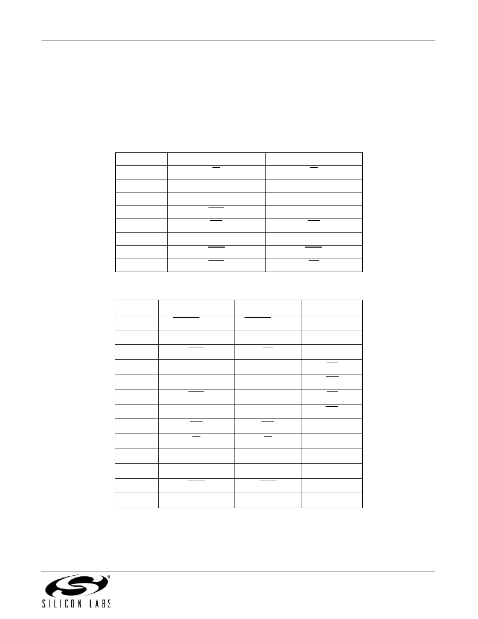
2.2.1. Interface Selection
The interface is selected during reset, as described in "2.1. Resetting the Device". Tables 12, 13, and 14 show the
functions of the affected pins for possible interface modes for 16-, 24- and 38-pin packages, respectively.
Table 12. Pin Functions vs. Interface Mode (SOIC-16)
Pin #
UART Mode
SPI Mode
3
RI
RI
5
RXD
MISO
6
TXD
MOSI
7
CTS
SCLK
11
INT
INT
14
ESC
ESC
15
DCD
DCD
16
RTS
SS
Table 13. Pin Functions vs. Interface Mode (TSSOP-24)
Pin #
UART Mode
SPI Mode
Parallel Mode
2
FSYNC (SSI)
FSYNC (SSI)
D6
3
CLKOUT (SSI)
CLKOUT (SSI)
A0
8
RTS
SS
D7
9
RXD
MISO
RD
10
TXD
MOSI
WR
11
CTS
SCLK
CS
15
AOUT
AOUT
INT
16
INT
INT
D0
17
RI
RI
D1
18
SDI (SSI)
SDI (SSI)
D2
22
ESC
ESC
D3
23
DCD
DCD
D4
24
SDO (SSI)
SDO (SSI)
D5