Country-dependent setup, Dc termination, An93 – Silicon Laboratories SI2493/57/34/15/04 User Manual
Page 133
AN93
Rev. 1.3
133
6.2. Country-Dependent Setup
Configuring the ISOmodem for operation in different countries is done easily with AT commands. In all but rare
instances, no hardware change is required (the exceptions being an optional maximum ringer impedance, a billing-
tone filter, etc.). For this reason, the ISOmodem is truly a global modem solution. Modem initialization commands
for various countries are presented in "6.2.2.1. Country Initialization Table". All U-register values are in
hexadecimal. The settings for different countries can be broken into three groups: call progress, dialing, and line-
interface control. Call-progress settings include filter coefficients, cadence data, and threshold values. Dialing
includes DTMF levels, thresholds, timing and pulse-dialing parameters. Line-interface settings include ac line
impedance, off-hook voltage and current characteristics, ringer sensitivity, and transmit levels. CID (Caller ID)
settings are discussed in a separate section. Tables 89–93 describe the registers and bits used for global
configuration and the functions performed by each. Many countries use some or all of the default FCC settings.
6.2.1. DC Termination
The ISOmodem offers a great deal of flexibility in setting dc termination. Several bits can be used to adapt to
particular country requirements and unusual line conditions. The dc termination control bits are shown in Table 89.
A detailed description of each bit is given in the relevant U-register description section of this manual. The following
discussion centers on the use of these bits alone or in combination to meet particular country requirements.
Quick connect
+PQC
+PSS
Reset
Z
U6E [4], U70 [7,5]
SAS detect
U9F–UA9
Self Test
&Tn, &Hn
40, 41
SMS
+FCLASS
+FRM
+FTM
V.29
+FCLASS
+FTM
+FRM
V.42/V.42b
+DR, %Cn, \Nn,
+DS
V.44*
+DS44, +DR
V.92
+MS
+PIG
*Note: Si2493 only.
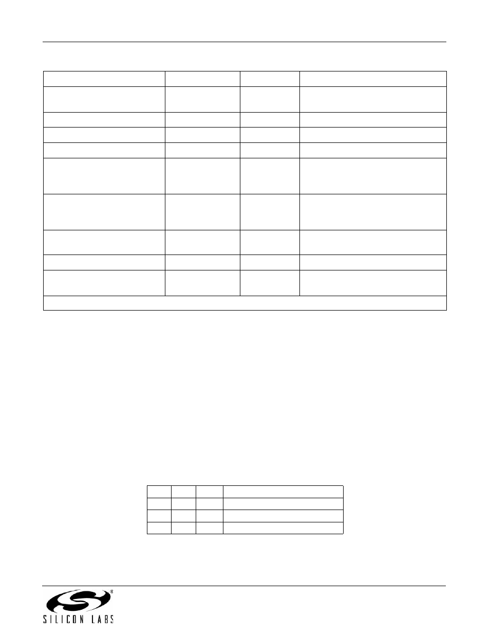
Table 89. DC Termination Control Bits
Reg
Bit
Val
Function
U67
7
DCR DC Impedance Select
U67
3:2
DCV
DC Termination Select
U7D
10
LLV
Special low-voltage mode
Table 88. Modem Feature vs. Hardware, AT Command and Register Setting (Continued)
Function/Feature
AT Commands
S Registers
U Registers