149, and 150 will gen, In table 149 and, Ed in table 150 – Silicon Laboratories SI2493/57/34/15/04 User Manual
Page 248: A n 9 3
A N 9 3
248
Rev. 1.3
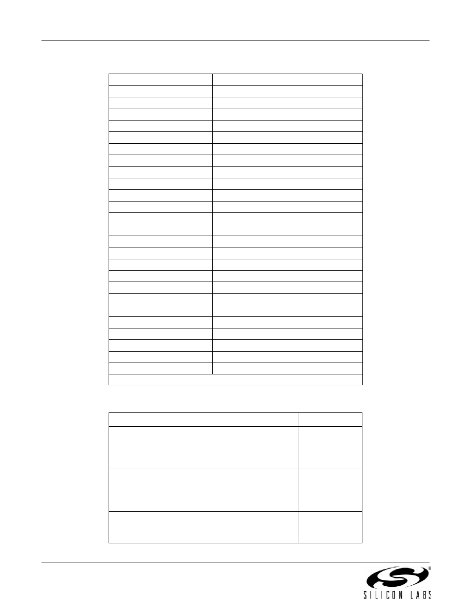
Table 149. Resistance across Components
Si3018/10
Resistance
FB1
< 1
FB2
< 1
RV1
> 20 M
R1
1.07 k
R2
150
R3
3.65 k
R4
2.49 k
R5
100 k
R6
100 k
R7
4.5 or 16 M
R8
4.5 or 16 M
R9
> 800 k
R10
536
R11
73
R12
< 1
R13
< 1
R15
< 1
R16
< 1
C1
> 20 M
C2
> 20 M
C3
> 3 M
C4
3.5 M
or 9.7 M
C7
2 M
or 5 M
C8
> 20 M
C9
> 20 M
Note:
If two values are given, the resistance measured is dependent on polarity.
Table 150. Voltages across Components with Diode Checker
Component
Voltage
Q1, Q3, Q4, Q5:
Base (red lead) to Emitter (black lead)
Base (red lead) to Collector (black lead)
(Verifies transistors are NPN)
0.6 V
0.6 V
Q2:
Emitter (red lead) to Base (black lead)
Collector (red lead) to Base (black lead)
(Verifies transistor is PNP)
0.6 V
0.6 V
Collector of Q2 (red lead)
to pin 1 of Si3018/10 (black lead)
If test fails, Z1 is reversed.
> 1 V