Programming examples, Quick reference, A n 9 3 – Silicon Laboratories SI2493/57/34/15/04 User Manual
Page 132
A N 9 3
132
Rev. 1.3
6. Programming Examples
The following programming examples are intended to facilitate the evaluation of various modem features and serve
as example command strings that can be used singly or in combination to create the desired modem operation.
6.1. Quick Reference
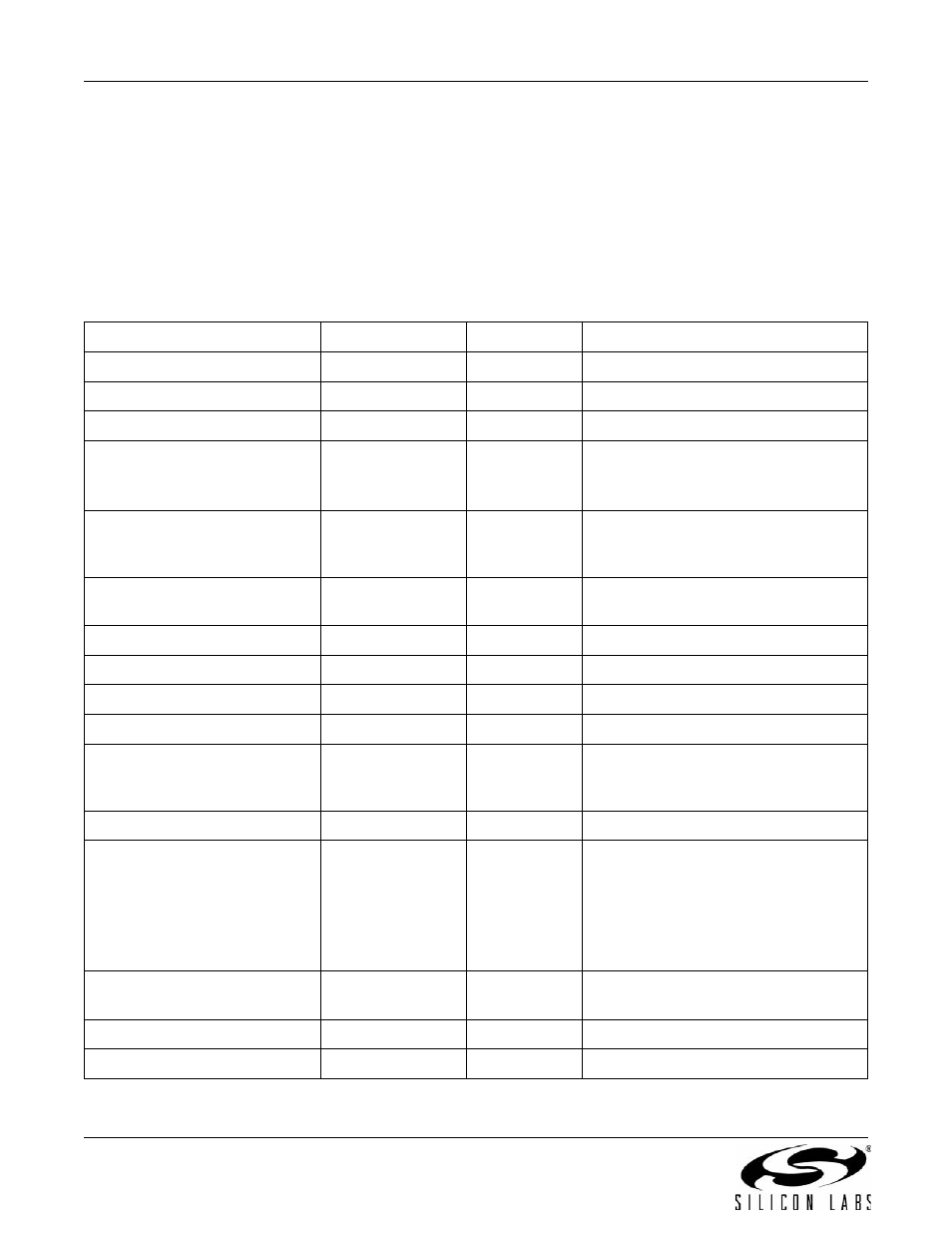
Table 88 summarizes the modem function/feature and the associated hardware pins, AT commands, S registers,
and U registers. When a command string is created to enable a particular feature, Table 88 should be reviewed to
make sure all necessary commands and registers have been considered.
Table 88. Modem Feature vs. Hardware, AT Command and Register Setting
Function/Feature
AT Commands
S Registers
U Registers
Autobaud
\T16, \T17
Blacklisting
%B
42, 43, 44
Type I Caller ID
+VCID, +VCDT
U70 [12,4]
Type II Caller ID
+PCW
+VCID
+VCIDR
Country-dependent settings
U0–U4C, U4D [10,1,0], U50–U52,
U62 [8], U67 [6, 3:2, 1, 0],
U68 [2, 1, 0], U69 [6, 5, 4]
DTE interface
En, \Bn, \Pn, \Qn,
\Tn, \U
DTMF dialing
D
6, 8, 14
U46–U48, U4E
EEPROM
:E, :M
Escape (parallel/SPI)
U70 [15], Parallel Register 1 [2]
Escape (UART)
\B6
12
U70 [13,15]
Intrusion detection
U6A [1], U69 [2], U70 [10, 2],
U76 [15:9, 8, 7:5, 4:0], U77 [15:12, 11],
U78 [15:14, 7:0], U79 [4:0], UAE
Line rate
&Gn, &Hn
Modem-on-hold
+PCW
+PMHF
+PMHR
+PMHT
+PMH
+ATO
Overcurrent detection
U67 [7], U70 [11, 3],
U77 [10, 9, 8:0], U79 [4:0]
Power control
&Z
24
U65 [13]
Pulse dialing
D
6, 8, 14
U37–U45, U4E