U53 (modem control register 2), U54 (calibration timing register), U62–u66 (daa control registers) – Silicon Laboratories SI2493/57/34/15/04 User Manual
Page 106: A n 9 3
A N 9 3
106
Rev. 1.3
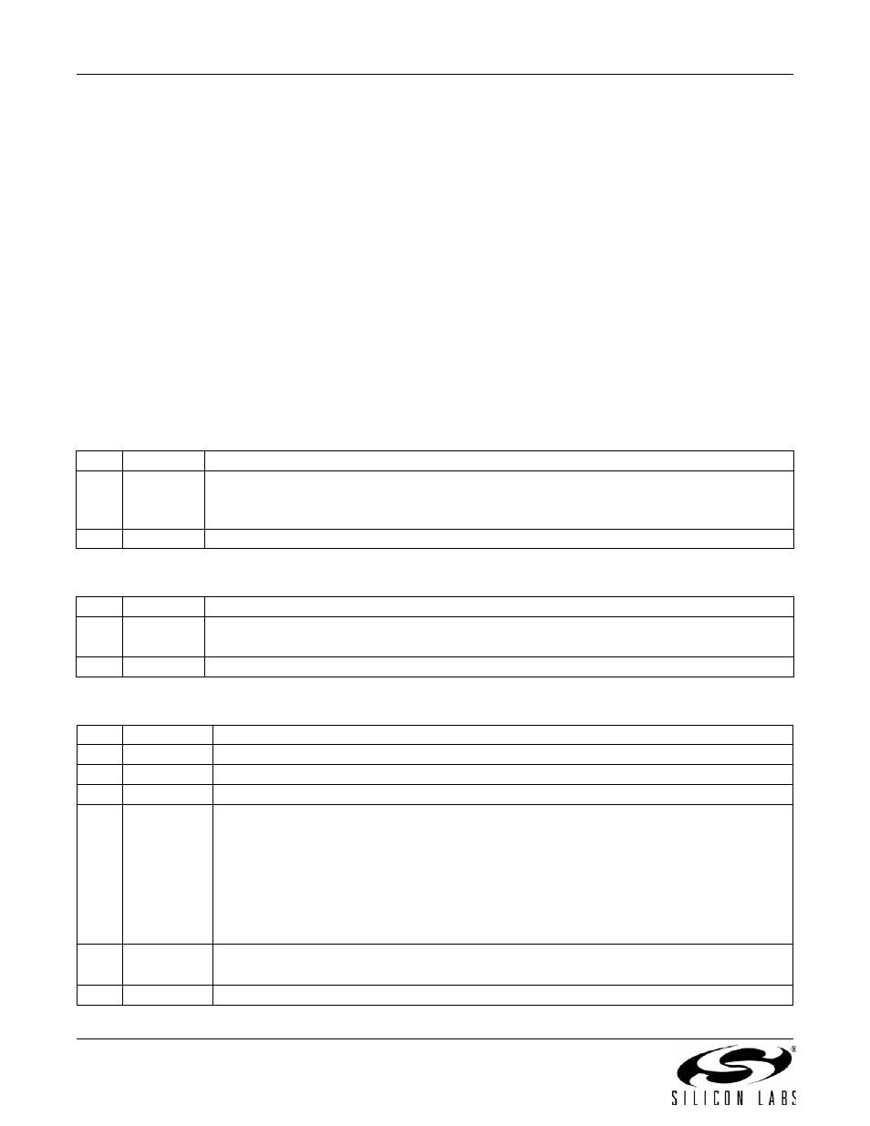
5.7.14. U53 (Modem Control Register 2)
U53 (MOD2) is a bit-mapped register with all bits, except bit 15, reserved (see Table 61). The AT&H11 command
sets the V.23 1200/75 bps mode. Bit 15 (REV) is used to enable V.23 reversing. This bit is set to 0 (disable
reversing) by default. Setting this bit to 1 enables reversing transmit and receive speeds. Reversing is initiated by
the modem in the “origination mode” (low speed TX and high speed RX). U53 resets to 0x0000 with a power-on or
manual reset.
5.7.15. U54 (Calibration Timing Register)
U54 (CALT) sets the time between off-hook and DAA calibration if timed calibration is enabled with the TCAL bit
(U7D, bit 12). The OHCT bits (15:8) control this timing in 32 ms units.
5.7.16. U62–U66 (DAA Control Registers)
U62 (DAAC1) is a bit-mapped register with only bits 1, 2, and 8 available. All other bits in this register are reserved
and must be set according to Table 63. U62 resets to 0x0804 with a power-on or manual reset.
Bit 1 (DL) = 1 or 0 causes digital loopback to occur beyond the isolation capacitor interface out to and including the
analog hybrid circuit. Setting bit 1 high enables digital loopback across the isolation barrier only. This setting is
used in conjunction with the AT&H and AT&T3 commands. DL must be set low for normal operation.
Bit 2 (FOH) controls when automatic Si3018/10 calibration takes place.
Table 61. U53 Bit Map
Bit
Name
Function
15
REV
V.23 Reversing.
0 = Disable.
1 = Enable.
14:0
Reserved
Read returns zero.
Table 62. U54 Bit Map
Bit
Name
Function
15:8
OHCT
Off-hook to calibration timing in 32 ms units. If enabled with TCAL (U7D bit 12), this value
controls the time between off-hook and DAA calibration.
7:0
Reserved
Must be set to zero.
Table 63. U62 Bit Map
Bit
Name
Function
15:12
Reserved
Must be set to zero.
11
Reserved
Must be set to one.
10:9
Reserved
Must be set to zero.
8
OHS2
On-Hook Speed 2
This bit, in combination with the OHS bit and the SQ[1:0] bits on-hook speeds specified
are measured from the time the OH bit is cleared until loop current equals zero.
OHS
OHS2
SQ[1:0]
Mean On-Hook Speed
0
0
00
Less than 0.5 ms
0
1
00
3 ms ±10% (meets ETSI standard)
1
X
11
26 ms ±10% (meets Australia spark quenching spec)
Note: The +GCI command does not modify OHS2, SQ[1:0].
7
Full 1
0 = Disable
1 = Enable. +3.2 dBm maximum into 600
(Si3018 only)
6:5
Reserved
Must be set to zero.