Rated in figure 42, Own in figure 43, A n 9 3 – Silicon Laboratories SI2493/57/34/15/04 User Manual
Page 246
A N 9 3
246
Rev. 1.3
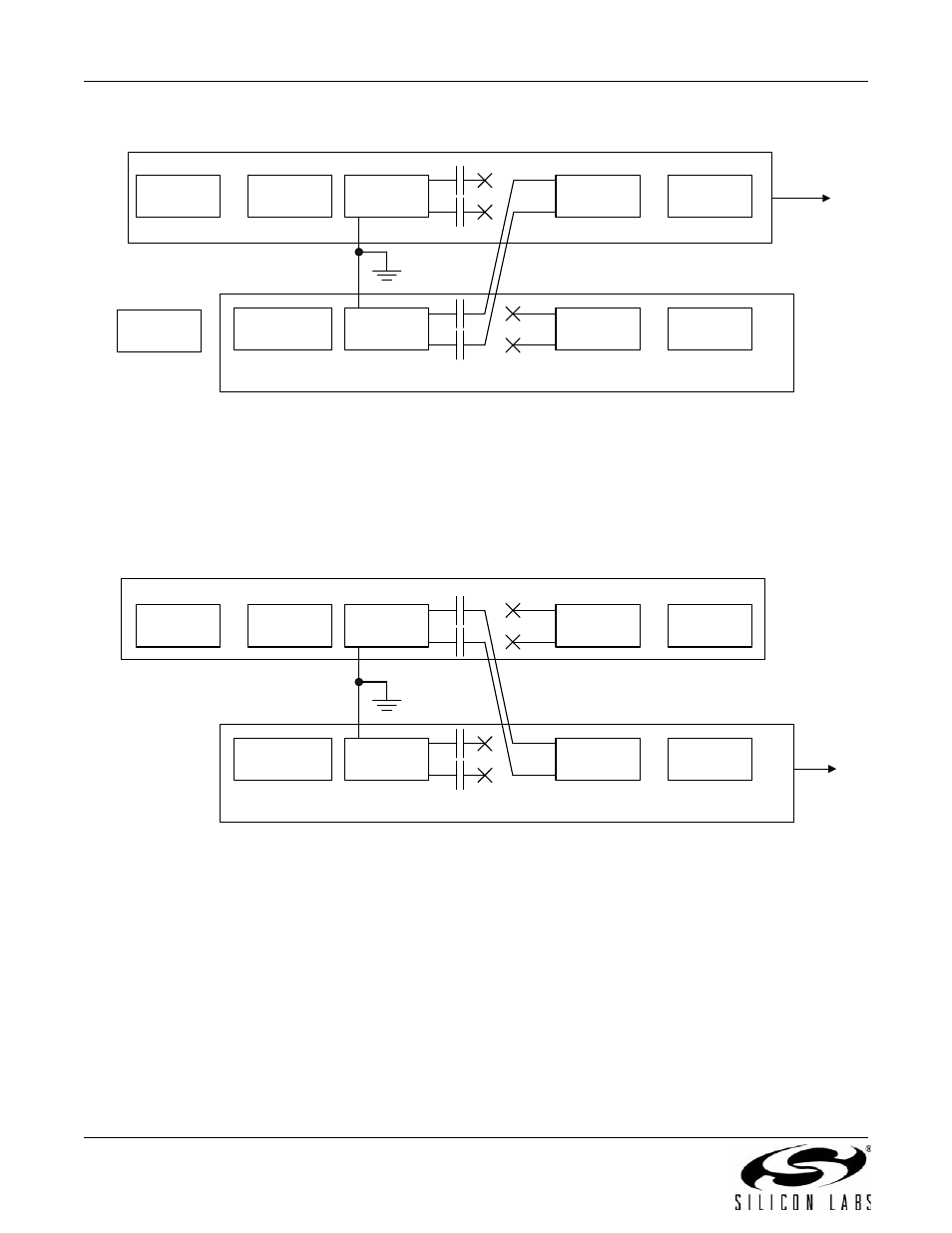
Figure 42. Test the Prototype Si3018/10 Circuitry
Figure 43. Verify Prototype Si3018/10 Failure
To
Phone
Line
Host
Controller
Host
UART
Si24xx
Si3018
Discretes
RS232
Transceiver
Si24xx
Si3018
Discretes
EVB
Connect the prototype ground to the EVB ground.
Lift prototype C1 and C2 and EVB C1 and C2 so the Si3018 is disconnected from the Si24xx on both modems.
Connect EVB C1 and C2 to the Si3018 pad of prototype system C1 and C2.
Connect the phone line to the RJ11 jack on the prototype system.
Use PC and HyperTerm and attempt to establish a modem connection.
PC
C2
C1
C2
Prototype System
C1
To
Phone
Line
Host
Controller
Host
UART
Si24xx
Si3018
Discretes
RS232
Transceiver
Si24xx
Si3018
Discretes
EVB
Connect the prototype ground to the EVB ground
Lift prototype and EVB C1 and C2 to decouple the line side from the DSP side. Do same on evaluation board.
Connect prototype system C1 and C2 to the Si3018 pad of EVB C1 and C2
Connect the phone line to the RJ11 jack on the EVB
Run the prototype system software to attempt a modem connection
C2
C1
C2
C1
Prototype System