5 transmit deviation limit alignment, Transmit deviation limit alignment -8 – Motorola SSETM 5000 User Manual
Page 78
November 11, 2004
6881094C12-A
5-8
Radio Alignment Procedures: Transmitter Alignments
8. Repeat Steps 2 through 7 for all frequencies.
9. Left-click the Program All button on the screen to dekey the radio and save the tuned values.
10. Left-click the Close button on the screen to return to the Transmitter Alignments menu.
5.5.5
Transmit Deviation Limit Alignment
This alignment procedure limits the modulation of a baseband signal. It is used for primary
modulation limiting.
This procedure needs to be performed at multiple frequencies to allow for proper alignment across
the entire RF band. The RF band is divided into frequency zones with a calibration point (value) in
each zone.
NOTE: This alignment is required after replacing (or servicing) the VOCON board or the transceiver
board.
To align the transmit deviation limit:
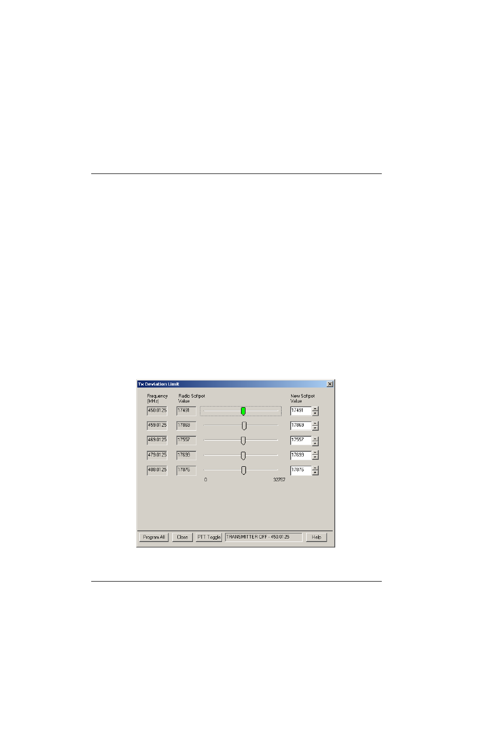
1. Select the TX Deviation Limit alignment screen. The screen indicates the transmit
frequencies to be used. See
2. Left-click the desired frequency field (starting with the highest frequency shown).
3. Left-click the PTT Toggle button on the screen to make the radio transmit. The screen
indicates whether the radio is transmitting.
4. Measure the transmitted signal deviation of the radio with your communications system
analyzer.
5. Adjust softpot value until the measured deviation is as close as possible to 2.83 kHz.
Figure 5-9. Transmit Deviation Limit Alignment Screen