Chapter 8 troubleshooting, 1 voltage measurement and signal tracing, 2 standard bias table – Motorola SSETM 5000 User Manual
Page 101: Chapter 8, Troubleshooting -1, Voltage measurement and signal tracing -1, Standard bias table -1, Table 8-1, Standard operating bias -1
Chapter 8 Troubleshooting
The purpose of this chapter is to aid in troubleshooting problems with the SSE 5000 radio. It is
intended to be detailed enough to localize the malfunctioning circuit and isolate the defective
component.
8.1
Voltage Measurement and Signal Tracing
It is always a good idea to check the battery voltage under load. This can be done by checking the
OPT_B+_VPP pin at the accessory connector (pin 8). The battery voltage should remain at or above
7.0 Vdc. If the battery voltage is less than 7.0 Vdc, then it should be recharged or replaced as
necessary prior to analyzing the radio.
In most instances, the problem circuit may be identified using a multimeter, an RF millivoltmeter,
oscilloscope (preferably with 100 MHz bandwidth or more), and a spectrum analyzer.
8.2
Standard Bias Table
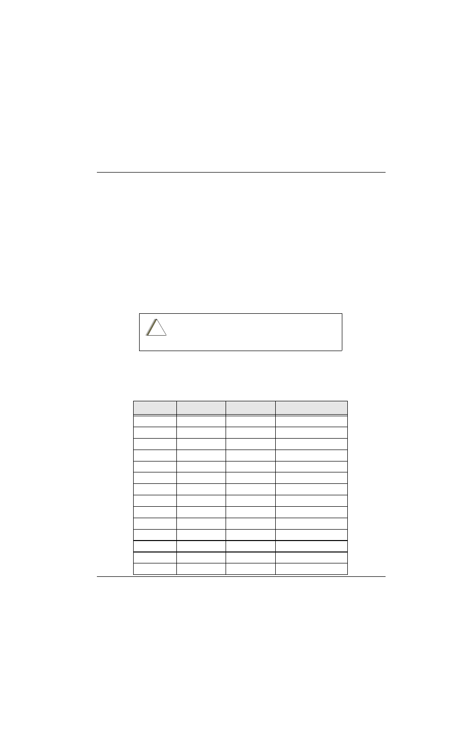
outlines some standard supply voltages and system clocks which should be present under
normal operation. These should be checked as a first step to any troubleshooting procedure.
When checking a transistor or module, either in or out of
circuit, do not use an ohmmeter having more than 1.5 Vdc
appearing across test leads or use an ohms scale of less than
x100.
Table 8-1. Standard Operating Bias
Signal Name
Nominal Value
Tolerance
VOCON Board Source
13 MHz
13 MHz
±1000 ppm
C303
FLIP_32K
32.768 kHz
±400 ppm
R337
CKIH
16.8 MHz
R615
16_8MHz
16.8 MHz
C607
POR
3.0 Vdc
±5%
R725
RESET_OUT
3.0 Vdc
±5%
D401, pin 1
VSW1
3.85 Vdc
±5%
Test point TP501
VSW2
1.85 Vdc
±5%
Test point TP500
FILT_B+
7.5 Vdc
6.0-9.0 Vdc
C523
V2
3.0 Vdc
±5%
R560
GCAP_B+
7.5 Vdc
6.0-9.0 Vdc
R581
UNSW_B+
7.5 Vdc
6.0-9.0 Vdc
B702
SW_B+
7.5 Vdc
6.0-9.0 Vdc
R587
VCC5
5.0 Vdc
±5%
R503
!
C a u t i o n