Figure 2-10. vocon board connector j102 -30, Table 2-10, Own in – Motorola SSETM 5000 User Manual
Page 52: Figure 2-10
November 11, 2004
6881094C12-A
2-30
Theory of Operation: VOCON Board
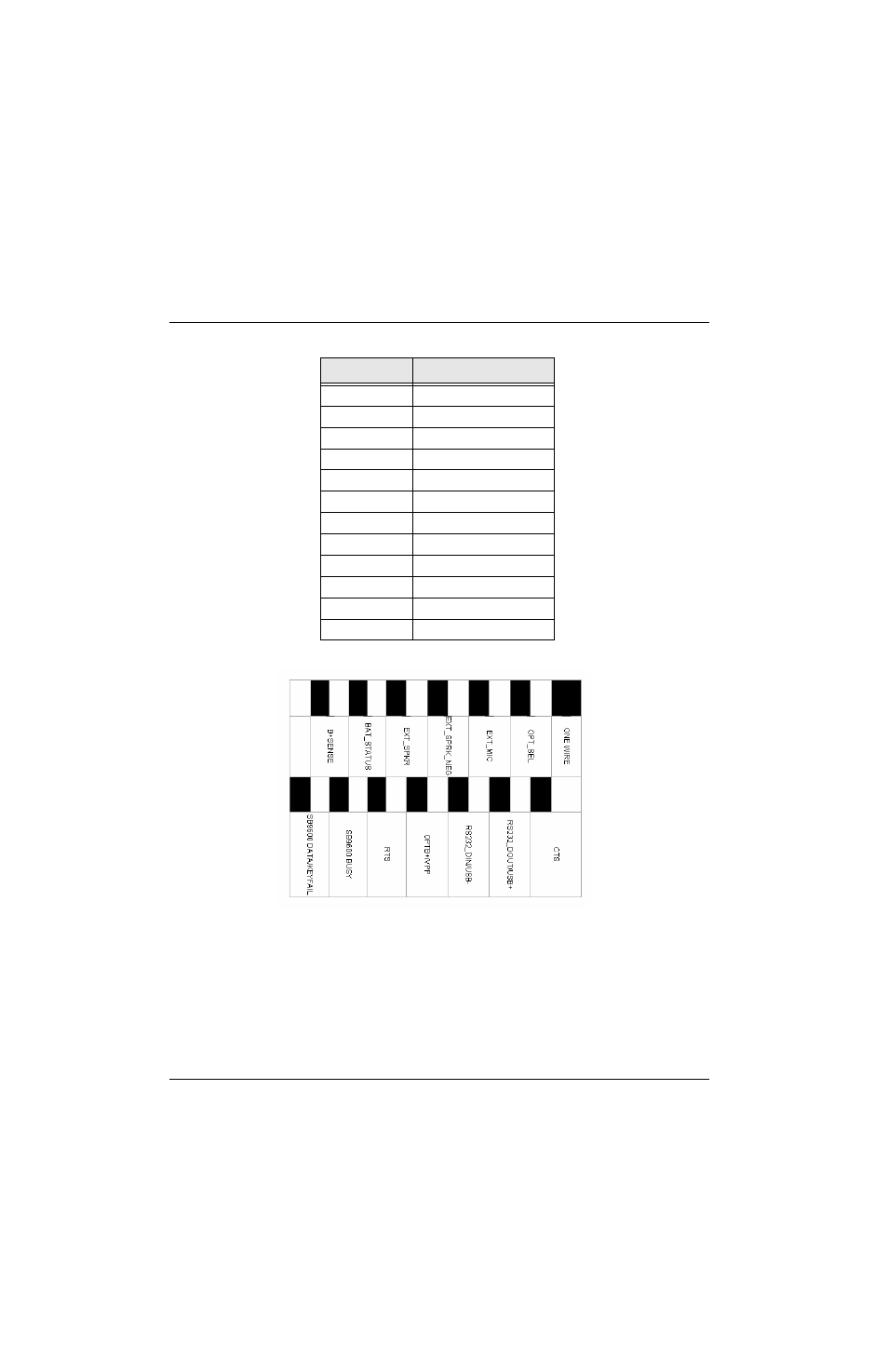
Figure 2-10. VOCON Board Connector J102
Most of the signals are extensions of circuits described in other areas of this manual. However, the
option-select pin is used to configure special modes: option-select 1 and option-select 2. This pin is
controlled by accessories connected to the universal connector.
Table 2-10. Pin Assignments for Universal Side Connector
Pin Number
Description
1
EXT_SPKR_NEG
2
EXT_SPKR_PLUS
3
LHDATA
4
EXT_MIC
5
CTS_OUT
6
LHBUSY
7
OPT_SEL
8
OPT_B+/VPP
9
RTSIN/KEYFAIL
10
1-WIRE
11
RS232_DOUT/USB+
12
RS232_DIN/USB-