4 transceiver board, 1 interconnections, 1 battery connector j3 – Motorola SSETM 5000 User Manual
Page 29: 2 vocon connector p1, Transceiver board -7 2.4.1, Interconnections -7, Battery connector j3 -7, Vocon connector p1 -7, Table 2-5, Table 2-6
6881094C12-A
November 11, 2004
Theory of Operation: Transceiver Board
2-7
2.4
Transceiver Board
The transceiver (XCVR) board performs the transmitter and receiver functions necessary to translate
between voice and data from the VOCON board and the modulated radio-frequency (RF) carrier at
the antenna. The transceiver board contains all the radio’s RF circuits for the following major
components:
• Receiver
• Transmitter
• Frequency Generation Unit (FGU)
2.4.1
Interconnections
This section describes the various interconnections for the transceiver board.
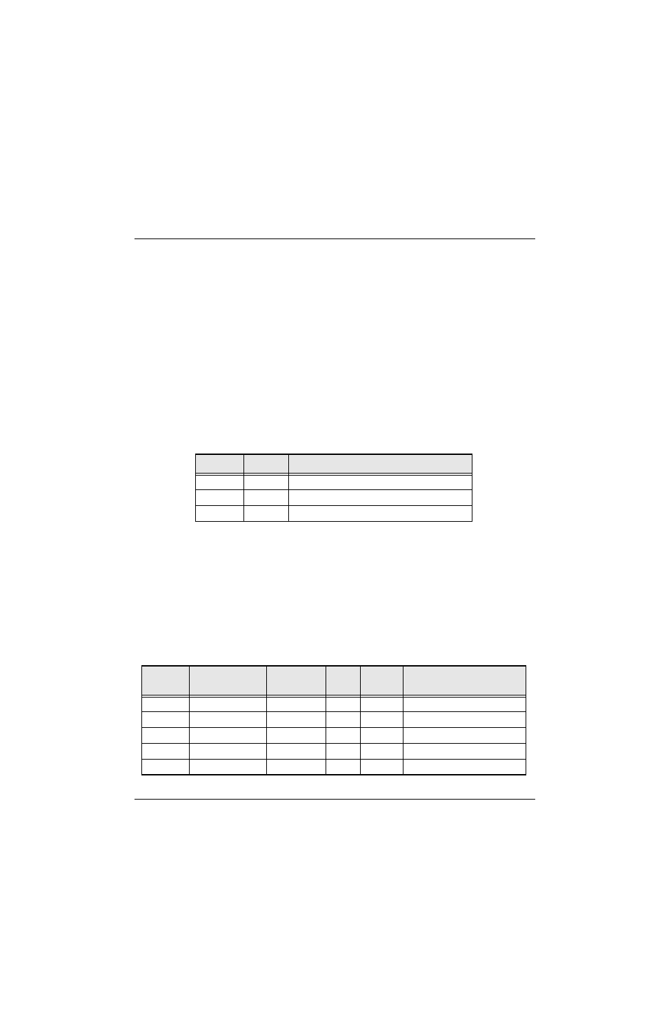
2.4.1.1 Battery Connector J3
Battery connector J3 consists of three gold-plated contacts on the printed circuit board that mate with
a B-plus connector assembly. Signal descriptions are in
2.4.1.2 VOCON Connector P1
VOCON connector P1 (located on the XCVR board) consists of 26 gold-plated pads for the 26-pin
compression connector, and one plated tool hole (pin 27) used for connector alignment. This is a
digital interface carrying DC power, control, and data between the XCVR and VOCON boards. P1
connects through the compression connector to P201 on the VOCON board.
lists the connector pins, their signals, and functions. SPI refers to the serial peripheral
interface, which is the control bus from the microprocessor. SSI is the serial synchronous interface
bus for data to and from the DSP. There is a RX SSI bus for demodulated data from the receiver and
a TX SSI bus for modulation data to the transmitter.
Table 2-5. Battery Connector J3
Pin No.
Signal
Description
1
BATT
Battery positive terminal, nominally 7.5 Vdc
2
BSTAT
Battery status, from battery to VOCON
3
BAT_RTN
Battery negative terminal, tied to PCB ground
Table 2-6. VOCON Connector P1
Pin No.
VOCON Signal
XCVR
Signal
XCVR
I/O
Type
Description
1
UNSW_B+
FUB+
O
dc
Fused B+ to VOCON
2
UNSW_B+
FUB+
O
dc
Fused B+ to VOCON
3
LOCK_DET*
LOCK
O
status
FGU lock detect
4
TX_SSI_DATA
TXTD
O
ssi
TX SSI data
5
SSI_CLK
RXCK
O
ssi
RX SSI clock