Chapter 2 theory of operation, 1 major assemblies, Chapter 2 – Motorola SSETM 5000 User Manual
Page 23: Theory of operation -1, Major assemblies -1, Figure 2-1. sse 5000 overall block diagram -1
Chapter 2 Theory of Operation
This chapter provides a detailed circuit description of the SSE 5000 transceiver and VOCON boards.
When reading the theory of operation, refer to the appropriate schematic and component location
diagrams located in the back of this manual. This detailed theory of operation can help isolate the
problem to a particular component.
The SSE 5000 radio is a dual-mode (digital/analog), microcontroller-based transceiver incorporating
a digital signal processor (DSP). The microcontroller handles the general radio control, monitors
status, and processes commands input from the keypad or other user controls. The DSP processes
the typical analog signals, and generates the standard signaling digitally to provide compatibility with
existing analog systems. In addition, the DSP provides digital modulation techniques, utilizing voice
encoding techniques with error correction schemes. This provides the user with enhanced range and
audio quality, all in a reduced bandwidth channel requirement. It allows embedded signaling, which
can mix system information and data with digital voice to support a multitude of system features.
The SSE 5000 radio operates within the UHF range (450 to 488 MHz).
2.1
Major Assemblies
The SSE 5000 radio includes the following major assemblies (
):
• VOCON Board — contains a dual-core processor which includes both the microcontroller unit
(MCU) and a digital signal processor (DSP) core, the processor’s memory devices, an audio
and power supply support integrated circuit (IC), a digital-support IC, and the audio power
amplifier.
• Transceiver (XCVR) Board — contains all transmit, receive, and frequency generation
circuitry, including the digital receiver back-end IC and the reference oscillator.
• Controls/Universal Flex — contains on/off/volume switch, channel select switch, push-to-talk
(PTT) switch, monitor button, several function-selectable switches, universal connector,
speaker, and microphone.
• Display — 112 pixels x 32 pixels bit-mapped, liquid-crystal display (LCD).
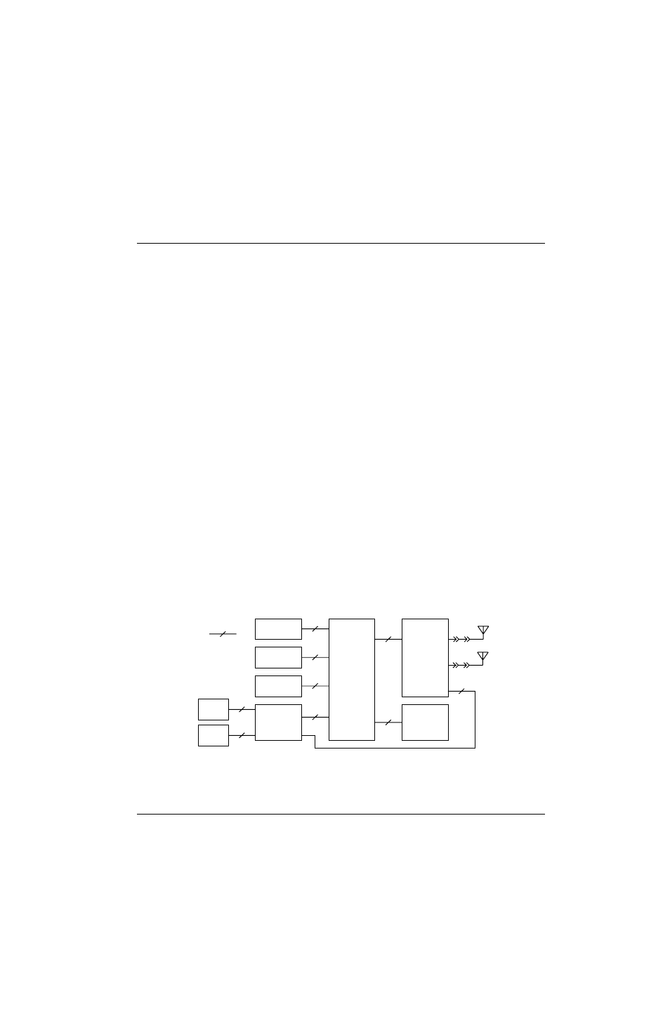
Figure 2-1. SSE 5000 Overall Block Diagram
Universal
Flex
Control
Top
Display
VOCON
Board
Transceiver
Board
Encryption
Module
(Optional)
7.5V
Battery
J102
J707
J301
J701
P201
P1
J1
J101
External
Accessory
Connector
12
4
20
20
12
26
40
3
Note:
Indicates 12
wires
Standard
Antenna
Remote
Antenna
J102
Internal Speaker
& Mic Flex
14
M102
3
MAEPF-27277-B