3 configuring the primary and slave units, User guide 20, Figure 18 configuration wizard – Minicom Advanced Systems DX System User Manual
Page 21: Cat5 cables
USER GUIDE
20
POWER
w
w
w
.m
in
ic
o
m
.c
o
m
ETHERNET
SERIAL
SERVICE
I
0
1
2
3
4
18
19
20
17
5
6
7
8
22
23
24
21
1
2
3
4
6
7
8
5
9
10
11
12
26
27
28
25
13
14
15
16
30
31
32
29
USER
SERVE R
POWER
w
w
w
.m
in
ic
o
m
.c
o
m
ETHE RNET
SERIAL
SERVICE
I
0
1
2
3
4
18
19
20
17
S ERVER
5
6
7
8
22
23
24
21
1
2
3
4
6
7
8
5
9
10
11
12
26
27
28
25
13
14
15
16
30
31
32
29
USE R
DX Central
1st level
DX Central units
Secondary level
To User
ports
To Server
ports
Ethernet
Straight cable
Network Hub / Switch
To User
ports
Ethernet
Straight cable
Ethernet
Straight
cable
POWER
w
w
w
.m
in
ic
o
m
.c
o
m
ETHERNET
SERIAL
SERV ICE
I
0
1
2
3
4
18
19
20
17
SERVE R
5
6
7
8
22
23
24
21
1
2
3
4
6
7
8
5
9
10
11
12
26
27
28
25
13
14
15
16
30
31
32
29
US ER
CAT5 cables
1 for each DX User
in the system
Up to 8 for 8 x 32
Up to 4 for 4 x 32
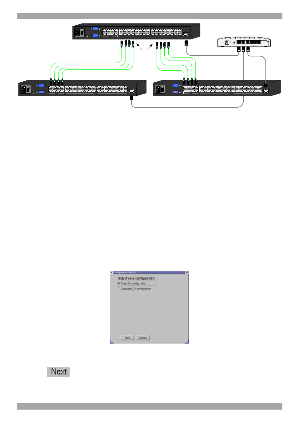
Figure 17 Cascaded DX Central units connected to a hub/switch
7.3 Configuring the primary and slave units
After connecting the cascaded DX Centrals you must configure them to be primary
or slave (secondary level) units.
To do so, connect a DX User to the each DX Central – primary and slave, as
explained above in section
4 on page 11. (Where you don’t have enough DX Users
for all the slaves, after configuring one slave connect the DX User to the next
slave.)
Power on the DX units in the following order:
1. Primary DX Central.
2. Slave/s DX Central(s).
3. The DX User connected to the primary DX Central.
The Configuration wizard appears on the DX User’s monitor, see Figure 18.
Figure 18 Configuration Wizard
1. Check Cascaded DX configuration.
2. Click
. The DX Network Configuration box appears. See Figure 19.