Minicom Advanced Systems KVM EXTENDER USB 5UM30167 User Manual
Kvm extender usb quick start guide, Syst em compon ents, T he kvm ext ender usb un its
w w w . m i n i c o m . c o m
International HQ
Jerusalem, Israel
Tel: + 972 2 535 9666
North American HQ
Linden, NJ, USA
Tel: + 1 908 486 2100
Technical support -
5UM30167 V1.1 7/10
KVM Extender USB
Quick Start Guide
KVM EXTENDER USB
1
1. In t rod uct ion
The KVM Extender USB system from Minicom is an advanced KVM extender that
performs the following functions:
· Extends KVM control over a computer up to a distance of 150m / 500ft
· Gives 2 users at 2 workstations control of 1 computer
· A 2-port KVM switch at the remote workstation
· Full USB keyboard and mouse control
2. Syst em compon ents
The KVM Extender USB system consists of:
· Transmitter
· Receiver
· 2 x VGA+USB cable
· 1 Power adapter for the Receiver
· 1 Screwdriver
· 8 non-stick rubber stops
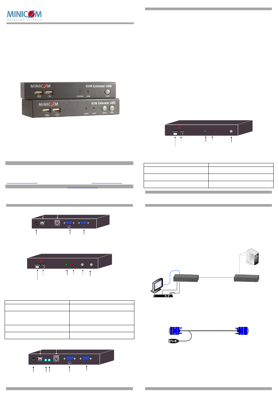
3. T he KVM Ext ender USB un its
The figures below illustrate the Transmitter unit.
LOCK
MINIC
O
M
KVM EXTENDER USB
LOCK
CONTROL
Keyboard
USB connector
Mouse USB
connector
Lock button
Local + Lock
LEDs
Figure 1 Transmitter front panel
3.1 Transmitter Button / LEDs
Button / LED
Function
Lock button
Press to keep control of the connected
computer at the Transmitter position
Control LED
Blinks when Transmitter position has control
of the Transmitter position computer
Lock LED
Blinks after either Transmitter or Receiver
position presses the Lock button for control
QUICK START GUIDE
2
CONTROL
POWER
SYSTEM
COMPUTER
Power connector
Local monitor
Computer cable
(Optional)
Control box
System cable
Figure 2 Transmitter back panel
The figures below illustrate the Receiver unit. The Receiver can be up to 150m / 500ft
away from the Transmitter.
Keyboard
USB connector
Mouse USB
connector
LOCK
MINIC
O
M
KVM EXTENDER USB
LOCK
LOCAL
LOCAL
Lock button
Local button
Local + Lock
LEDs
Figure 3 Receiver front panel
3.2 Receiver Buttons / LEDs
Button / LED
Function
Lock button
Press to lock control of the Transmitter
computer at the Receiver
position
Local button
Press to toggle control between the local
Receiver computer and the remote
Transmitter computer (see also section 8.1 on
page 6)
Lock LED
Blinks after either Transmitter or Receiver
position presses the Lock button
Local LED
Blinks when Receiver
position has control of
the Receiver
position computer
Power connector
CONTROL
POWER
SYSTEM
COMPUTER
Eq
Luminance +
Equalization
selector
Lu
(Optional)
Control box
System cable
Local monitor
Computer cable
Figure 4 Receiver back panel
KVM EXTENDER USB
3
4. Pre- installat ion in st ructio ns
Place cables away from fluorescent lights, air conditioners, and machines that are
likely to generate electrical noise.
5. Co nnect ing t he Syst em
When using the system as an extender, extending KVM control from the computer up
to a distance of 150m/500ft, connect the system as in Figure 5. The connections are
explained below.
Receiver
Transmitter
Extended User
position
CAT5 cable - 150m/500ft
VGA + USB cable
Figure 5 KVM Extender USB as an extender
5.1 Connecting the Transmitter
Connect a VGA + USB cable - illustrated below - to the Transmitter and a computer.
Connect the HD15 connector to the Transmitter Computer port and connect the VGA
and USB connectors to the local computer Monitor and USB ports.
Figure 6 VGA + USB cable
5.2 Connecting a KVM workstation to the Receiver
Connect a KVM workstation to the Receiver. Connect a keyboard and mouse to the
Receiver Keyboard and Mouse USB ports. Connect a monitor to the Receiver Monitor
port.