1 connecting with an ethernet crossover cable, 2 connecting to a network hub/switch, Dx central - 1 – Minicom Advanced Systems DX System User Manual
Page 20: Level dx central - secondary level, Dx system 19
DX SYSTEM
19
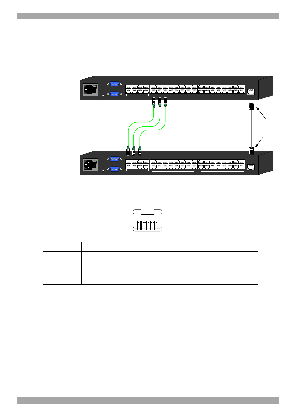
7.1 Connecting with an Ethernet Crossover cable
To connect a secondary level DX Central with an Ethernet Crossover cable:
Connect the Ethernet Crossover cable connectors to the Ethernet ports of the 2 DX
Centrals units, as illustrated in Figure 16.
POWER
w
w
w
.m
in
ic
o
m
.c
om
ETHERNET
SERIAL
SERVICE
I
0
1
2
3
4
18
19
20
17
SERVER
5
6
7
8
22
23
24
21
1
2
3
4
6
7
8
5
9
10
11
12
26
27
28
25
13
14
15
16
30
31
32
29
USER
POWER
w
w
w
.m
in
ic
om
.c
o
m
ETHERNET
SERIAL
SERVICE
I
0
1
2
3
4
18
19
20
17
SERVER
5
6
7
8
22
23
24
21
1
2
3
4
6
7
8
5
9
10
11
12
26
27
28
25
13
14
15
16
30
31
32
29
USER
DX Central
- 1
st
level
DX Central
- Secondary level
Cascade
To User
ports
To Server
ports
Ethernet
Crossover
cable
CAT5 cables
1 for each DX User in
the system
Up to 8 for 8 x 32
Up to 4 for 4 x 32
To
Ethernet
ports
Figure 16 Cascaded DX Central units connected with a Crossover cable
The table below shows the Ethernet RJ 45 Connector pin-out.
1
8
Pin
Assignment
Pin
Assignment
1
TX +
5
Not connected
2
TX -
6
RX -
3
RX +
7
Not connected
4
Not connected
8
Not connected
7.2 Connecting to a network hub/switch
To connect to a network hub/switch:
Connect Ethernet Straight cables to the Ethernet ports of the DX Centrals units, as
illustrated in Figure 17.