2 dx user units, Dx system 9, Figure 3 dx 832 central unit rear panel – Minicom Advanced Systems DX System User Manual
Page 10: Minic o m, Figure 4 dx user front panel, Figure 5 dx user rear panel ports
DX SYSTEM
9
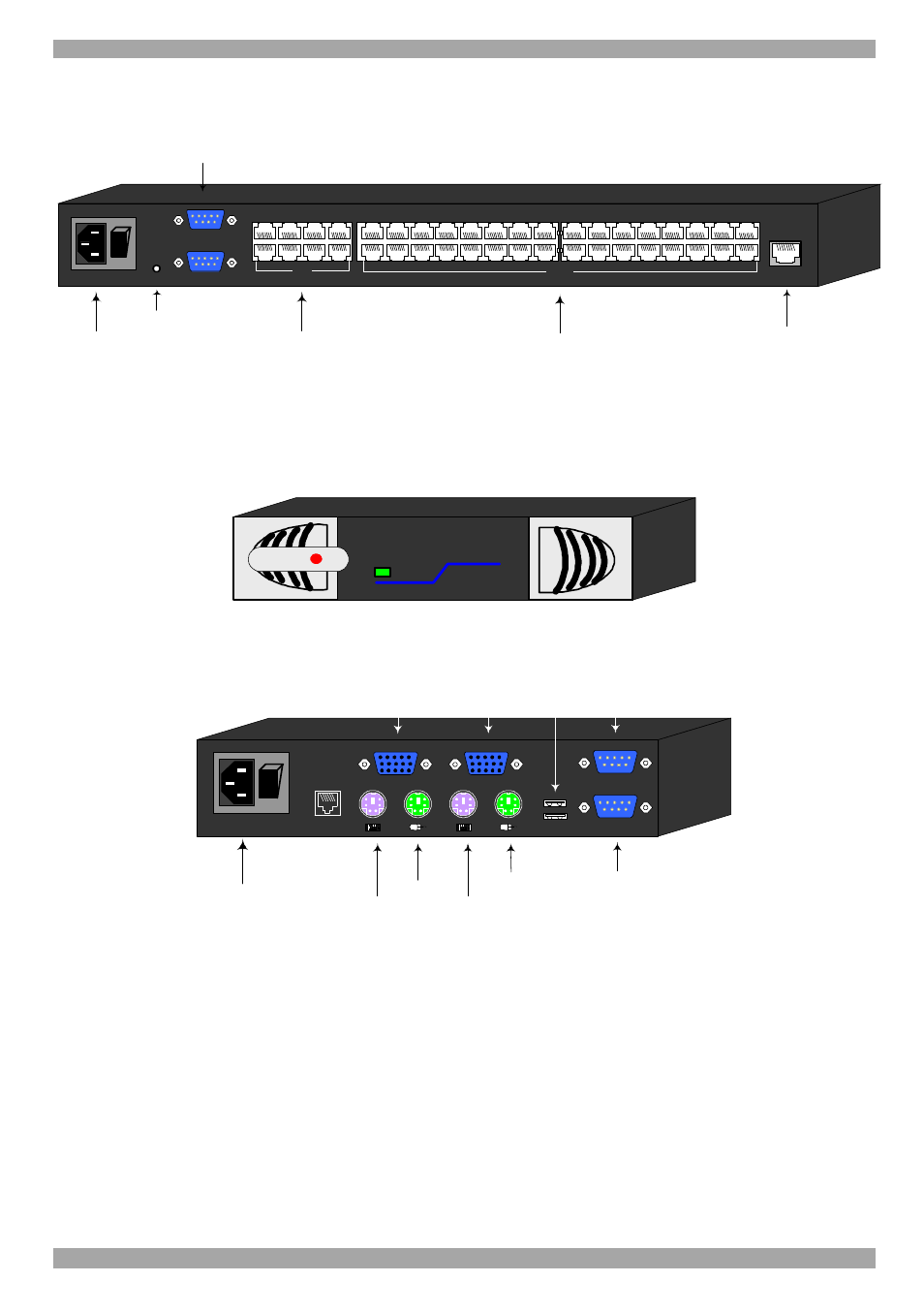
The figure below illustrates the rear panel of the DX 832 Central unit. The DX 432
Central model is the same but with only 4 User ports.
Power
connector
RS232 Service
port
User ports
POWER
100-250 VAC 50/60 Hz
w
w
w
.m
in
ic
o
m
.c
o
m
Reset
button
Ethernet
ETHERNET
SERIAL
SERVICE
I
0
1
2
3
4
18
19
20
17
SERVER
5
6
7
8
22
23
24
21
1
2
3
4
6
7
8
5
9
10
11
12
26
27
28
25
13
14
15
16
30
31
32
29
Server ports
RS232 Serial
port
USER
Figure 3 DX 832 Central unit rear panel
3.2 DX User units
Figure 4 illustrates the front panel of the DX User unit.
MINIC
O
M
Power
DX
User
Figure 4 DX User front panel
The figure below illustrates the rear panel of the DX User unit.
SYSTEM
Power
connector
POWER
100-250 VAC 50/60 Hz
w
w
w
.m
in
ic
o
m
.c
o
m
I
0
Keyboard
Mouse
Monitor
Computer
Keyboard port
Computer
Mouse port
Computer
Video card
USB
LOCAL COMPUTER
TERMINAL
CONSOLE
COMPUTER
USB
ports
RS232
Terminal port
RS232 port to
Local computer
Figure 5 DX User rear panel ports