Checklist for basic operational functionality, Owner 's manual, Power-up procedure – MACKIE DIGITALXBUS X.200 User Manual
Page 55: Input source, Channel eq and dynamics, Signal routing, Monitor speaker
55
Owner's Manual
Owner
's Manual
Checklist for Basic Operational
Functionality
Basic system functionality depends on the ac-
curate selection of a few key items. Work through
this checklist to verify console settings. The previ-
ous chapters provide an explanation of each item.
This checklist simply provides a mental road map to
verify proper functionality.
Input Source
❏ Mic/DI
❏ Line/Instrument
Channel EQ and Dynamics
❏ EQ
❏ Compression
❏ Gate
Signal Routing
❏ To
L/R
❏ To
Tape
❏ To
Bus
Monitor Speaker
❏
Control Room selection correct
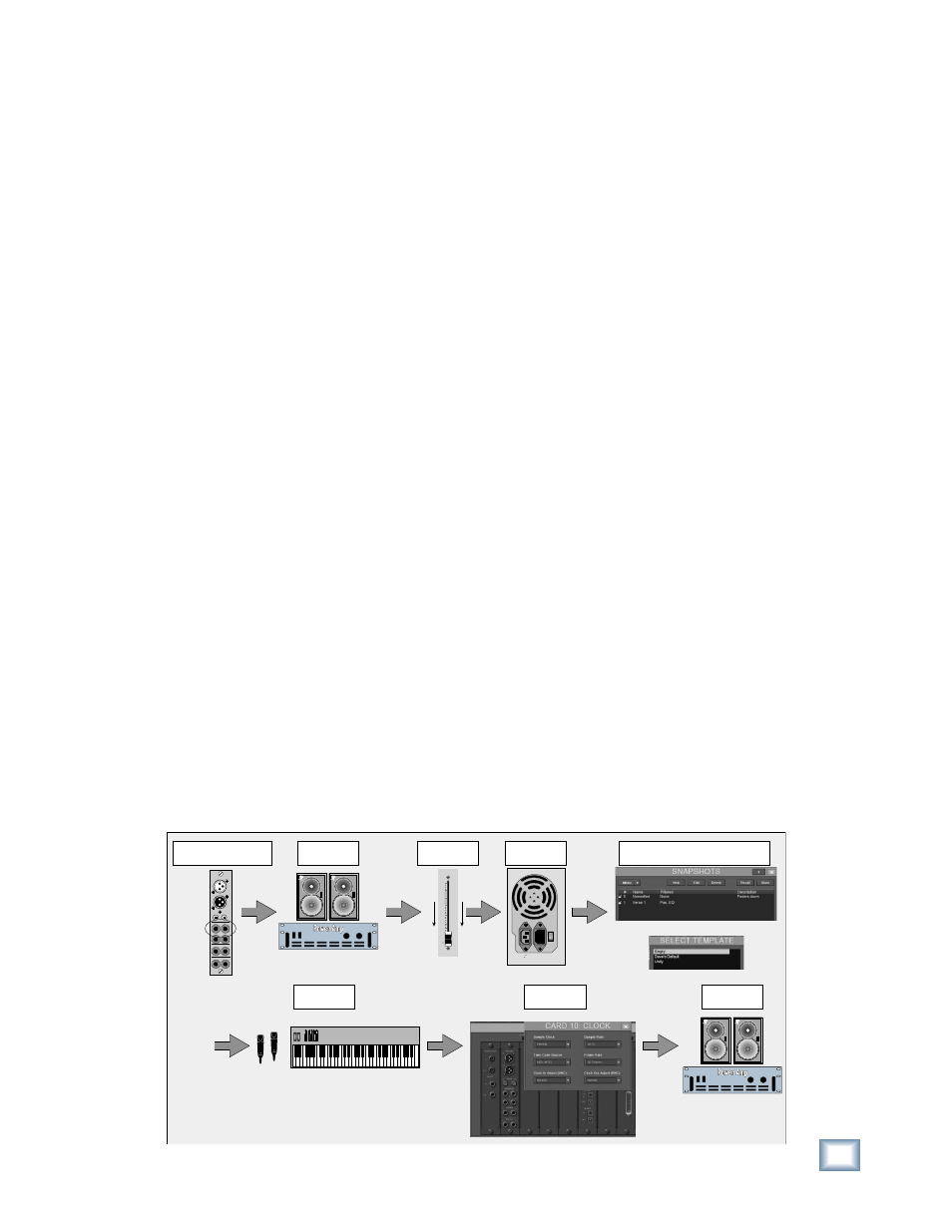
Power-up Procedure
A well-thought-out power-up procedure saves
wear and tear on all your gear. This procedure helps
minimize the opportunity for equipment damage
while maximizing the chance of success. Refer to
Figure 4-1 for a Fast Track Graphic representation
of this procedure.
❏ Connect Speakers Out A to an amplifi er/monitor
speakers combination or a pair of powered
monitors
❏ Amplifi cation system off: power amps or pow-
ered monitors
❏ Master Fader down
❏ Switch Console Power on
• The Digital X Bus will load the untitled tem-
plate, which is a Startup fi le with default settings,
if a user-set template has not yet been specifi ed.
❏ Open and load a snapshot or a session (optional)
• It’s a good idea to keep a snapshot of each
working confi guration as a starting point: track-
ing, overdubs, symphony, grunge band, etc.
❏ Connect all mics and instruments
• Be sure all channel faders are down.
• Turn Master Fader down.
• Turn Speaker level down.
❏ Set up sample clock
• Verify consistent sample rate settings
throughout all digital multitrack recording
devices.
• Word clock and digital data transfer connec-
tions are very important to the effi ciency and
functionality of any digital system. Verify them.
• Most systems work best when the Digital X
Bus is the Master word clock source. Use the
Sync card to send word clock to slave devices.
❏ Turn
amplifi cation system on
• Wait until all other gear is powered up before
turning on the monitor system.
❏ Enjoy the creative process
5
U
5
10
20
30
40
50
60
10
dB
115V 9
V 9amp 6
p 60Hz
230V 4.5
V 4.5amp 5
p 50Hz
1100
1100W M
W Max
Synth
Or
Amp or Powered
Monitors Off
Connect Mix Out Card (Speaker A)
to Amp or Powered Monitors
Connect Instruments
and Microphones
Master L/R
Fader Down
Console
Power On
Select a Starting Snapshot (Windows > Snapshots) or
Open Your Master Template (File > New Session)
Set Sample
Clock
A
B
MIX OUT CARD
SPDIF
SPEAKERS
PHONES
MIX OUT
IN
OUT
IN
L
R
1
2
L
R
L
R
OUT
AES/EBU
Amp or Powered
Monitors On
Figure 4-1 Power-up Procedure