Servicing instructions, Replacing parts, Ignition lead – Stovax Studio 22 User Manual
Page 34: Gas valve
34
SERVICING INSTRUCTIONS
REPLACING PARTS
13
AR1349
• Replace with a new electrode. Do not over-tighten the
nut; this could break the component
• Replace the ignition lead by pushing the spade connector
onto the terminal (electrode)
14
AR1874
A
B
8.4 Pilot Injector
• Undo the pilot pipe from the gas valve and from the
underside of the pilot burner, Diagram 14, arrow A
• Remove the pipe and the injector drops out from the
burner
8.5 Thermocouple
• Disconnect the thermocouple from the gas
valve/interrupter, Diagram 14, Arrow B
• Undo the thermocouple nut in the back of the pilot
bracket half a turn. This releases the thermocouple.
When replacing with a new thermocouple, take care to
bend the new component to the same shape as the
thermocouple just removed.
To refit the thermocouple into the pilot bracket, ensure it is
pushed fully into the hole. There is a stop on the
thermocouple to set the height.
• Lock the retaining nut just enough to grip the
thermocouple
• Connect the thermocouple to the valve/interrupter and
take care not to over-tighten
9. IGNITION LEAD
15
AR1872
A
B
9.1 To replace the ignition lead:
• Release the Main Control Assembly and tilt backwards,
see Section 7 above
• Remove the ignition lead from the control box, Diagram
15, Arrow A
• Remove the ignition lead from the electrode,
Diagram 15, Arrow B
Note the direction of the lead. The new lead must follow
exactly the same route.
NOTE: THE IGNITION LEAD MUST NOT PASS IN
FRONT OF THE CONTROL BOX AS THIS CAN DAMAGE
THE SENSITIVE ELECTRONICS.
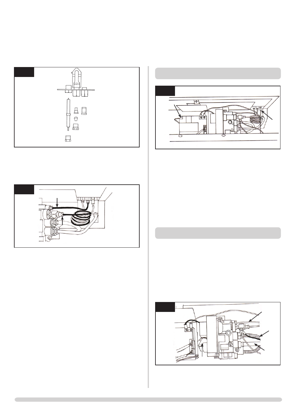
10. GAS VALVE
10.1 To change the gas valve:
• Remove the control assembly, Section 7
• Release the gas inlet pipe, Diagram 16, Arrow A
• Remove the thermocouple from the interrupter block
and release the second thermo current cables
•
• Release the pilot pipe, Diagram 16, B
• Release the injector feed pipe, Diagram 16, C
• Remove the wire cable, Diagram16, D
• Remove the two screws
The valve can now be freed.
16
AR1873
B
A
C
D