Installation instructions, Installation – Stovax Studio 22 User Manual
Page 26
26
40
AR2124
A
D
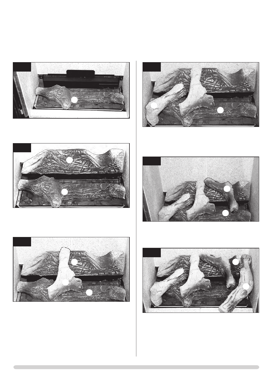
10.6 Put the groove in the base of Log E into the indent on the
right of Log A. The left branch rests on the upper end of Log
C, Diagram 41.
41
AR2125
A
E
10.7
Log F rests against Log B at its far right end, between Log
B and the side panel. The front end of Log F sits on the
front panel, see Diagram 42
42
AR2126
B
F
When closing the door ensure the door catches are fully
engaged
:
• Slide the allen key into the gap between the door and
frame and locate the catch of the lower lock
• Push the allen key DOWN
• Slide the allen key into the gap and locate the upper lock
• Push the allen key UP
INSTALLATION INSTRUCTIONS
INSTALLATION
37
AR2121
A
10.3
Place Log B on the ledge at the rear of the fire, Diagram
38.
38
AR2122
A
B
10.4
Put Log C so that the back end sits in the groove in the
rear of Log B and the front left rests in the cut-out groove
in Log A, Diagram 39.
39
AR02123
A
B
C
10.5 Position Log D so that the underneath rests in the groove of
Log A, and the triangular groove in the base of Log D fits
into the corner of the burner, Diagram 40.