Installation instructions, Site requirements, Flue options rear exit (8708) – Stovax Studio 22 User Manual
Page 13: 2 top flue up & out with additional bend
13
2. FLUE OPTIONS
REAR EXIT (8708)
• Cut to length as required on site
1
AR0630
200 mm min
500 mm max
Guard Supplied.
TOP EXITS
2.1 TOP FLUE UP & OUT kIT (8534)
This flue is vertical from the top of the appliance then
horizontally out. (See Diagram 2). The basic kit comprises:
1 x 200mm vertical length
1 x 500mm terminal length (cut to length on site)
1 x 90° elbow
1 x wall plate
1 x 70mm restrictor
1 x 60mm restrictor
2
AR1671
NOTE:
The start of the bend to the centre line of horizontal flue
is 170mm.
The centre line of vertical flue to end of bend is 220mm.
INSTALLATION INSTRUCTIONS
SITE REQUIREMENTS
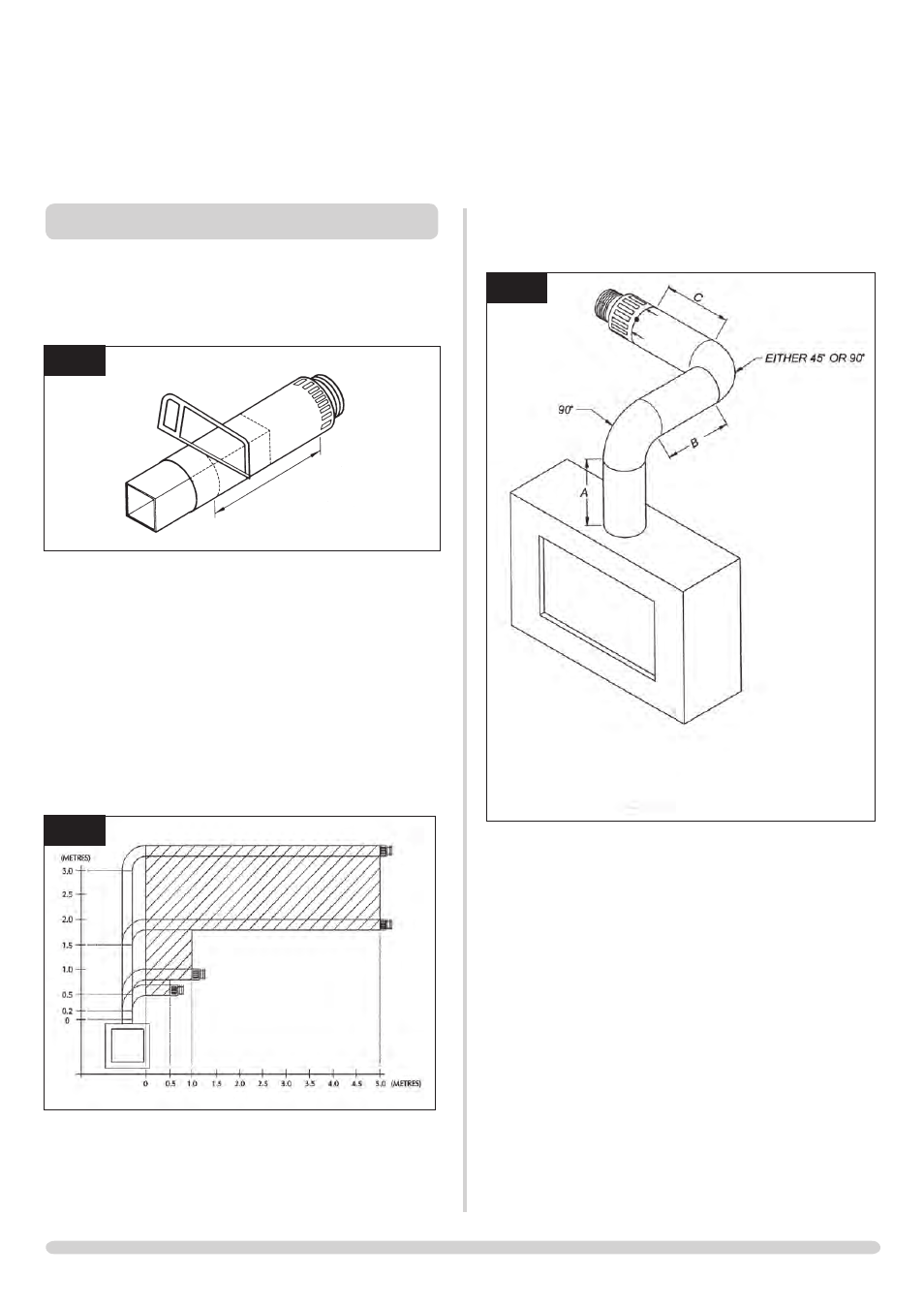
2.2 TOP FLUE UP & OUT WITH ADDITIONAL
BEND
3
AR1672
When A = 1.0 to 1.499 metes B & C = 1.0 metres
maximum
When A = 1.499 metres to 3.0 metres B & C = 4.0
metres maximum
Any additional bend may be used on the horizontal section
(either 45° or 90°), but the overall horizontal flue run will
be reduced. Refer to Diagram 3.