4 neutral voltage (fundamental) accuracy, Neutral voltage (fundamental) accuracy -4 – GE 489 User Manual
Page 216
7-4
489 Generator Management Relay
GE Multilin
7.2 HARDWARE FUNCTIONAL TESTS
7 TESTING
7
7.2.3 GROUND (1 A), NEUTRAL, AND DIFFERENTIAL CURRENT ACCURACY
The specification for neutral, differential and 1 A ground current input accuracy is
±0.5% of 2 × CT. Perform the steps below
to verify accuracy.
1.
Alter the following setpoints:
S2 SYSTEM SETUP
Ö
CURRENT SENSING
ÖØ
GROUND CT:
"1A Secondary"
S2 SYSTEM SETUP
Ö
CURRENT SENSING
ÖØ
GROUND CT RATIO:
"1000:1"
S2 SYSTEM SETUP
ÖØ
CURRENT SENSING
Ö
PHASE CT PRIMARY:
"1000 A"
S5 CURRENT ELEMENTS
ÖØ
PHASE DIFFERENTIAL
Ö
PHASE DIFFERENTIAL TRIP:
"Unlatched"
S5 CURRENT ELEMENTS
ÖØ
PHASE DIFFERENTIAL
ÖØ
DIFFERENTIAL TRIP MIN. PICKUP:
"0.1 x CT"
2.
Note: the last two setpoints are needed to view the neutral and the differential current. The trip element will operate
when differential current exceeds 100 A.
3.
Measured values should be
±10 A. Inject (I
A
only) the values shown in the table below into one phase only and verify
accuracy of the measured values. View the measured values in:
A2 METERING DATA
Ö
CURRENT METERING
or press the
key to view the current values when differential trip element is active.
7.2.4 NEUTRAL VOLTAGE (FUNDAMENTAL) ACCURACY
The specification for neutral voltage (fundamental) accuracy is
±0.5% of full scale (100 V). Perform the steps below to verify
accuracy.
1.
Alter the following setpoints:
S2 SYSTEM SETUP
ÖØ
VOLTAGE SENSING
ÖØ
NEUTRAL VOLTAGE TRANSFORMER:
"Yes"
S2 SYSTEM SETUP
ÖØ
VOLTAGE SENSING
ÖØ
NEUTRAL V.T. RATIO:
"10.00:1"
S2 SYSTEM SETUP
ÖØ
GEN. PARAMETERS
ÖØ
GENERATOR NOMINAL FREQUENCY:
"60 Hz"
2.
Measured values should be
±5.0 V. Apply the voltage values shown in the table and verify accuracy of the measured
values. View the measured values in:
A2 METERING DATA
ÖØ
VOLTAGE METERING
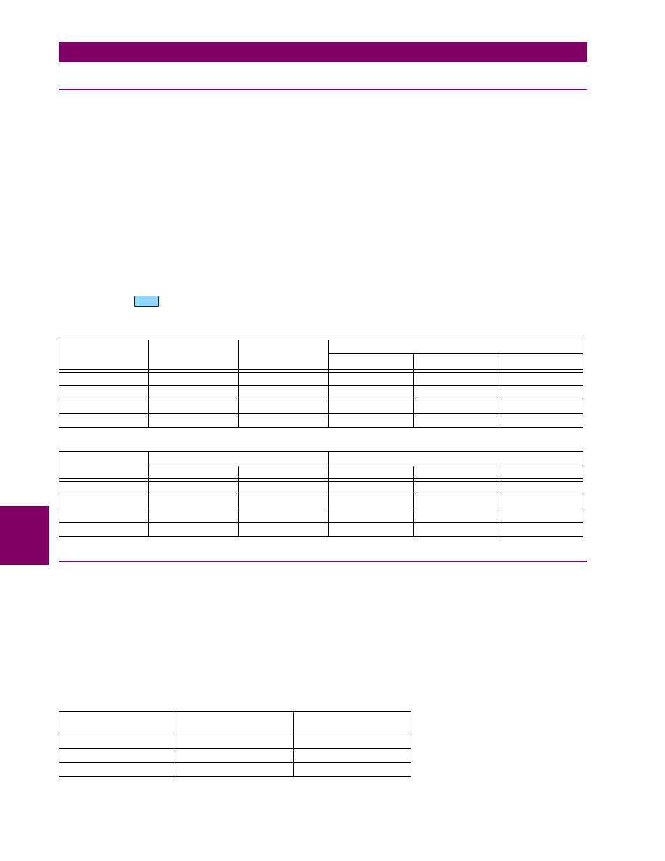
Table 7–1: NEUTRAL AND GROUND CURRENT TEST RESULTS
INJECTED
CURRENT
1 A UNIT
EXPECTED
CURRENT
READING
MEASURED
GROUND
CURRENT
MEASURED NEUTRAL CURRENT
PHASE A
PHASE B
PHASE C
0.1 A
100 A
0.2 A
200 A
0.5 A
500 A
1 A
1000 A
Table 7–2: DIFFERENTIAL CURRENT TEST RESULTS
INJECTED
CURRENT
EXPECTED CURRENT READING
MEASURED DIFFERENTIAL CURRENT
DIFF. PHASE A
DIFF PHASE B,C
PHASE A
PHASE B
PHASE C
0.1 A
200 A
100 A
0.2 A
400 A
200 A
0.5 A
1000 A
500 A
1 A
2000 A
1000 A
APPLIED NEUTRAL
VOLTAGE AT 60 HZ
EXPECTED NEUTRAL
VOLTAGE
MEASURED NEUTRAL
VOLTAGE
10 V
100 V
30 V
300 V
50 V
500 V
NEXT