GE 489 User Manual
Page 13
GE Multilin
489 Generator Management Relay
1-5
1 INTRODUCTION
1.2 SPECIFICATIONS
1
RS485 Baud Rates:
300, 1200, 2400, 4800, 9600, 19200
RS232 Baud Rate:
9600
Parity:
None, Odd, Even
Protocol:
Modbus
®
RTU / half duplex, DNP 3.0
ANALOG CURRENT OUTPUT
Type:
Active
Range:
4 to 20mA, 0 to 1 mA
(must be specified with order)
Accuracy:
±1% of full scale
4 to 20 mA max. load:
1.2 k
Ω
0 to 1mA max. load:
10 k
Ω
Isolation:
36 Vpk
(isolated with RTDs and analog inputs)
4 Assignable Outputs:
Phase A, B, C output current
3 phase average current
negative sequence current
generator load
hottest stator RTD
hottest bearing RTD
RTD # 1 to 12
AB voltage
BC voltage
CA voltage
average phase-phase voltage
volts/hertz
frequency
3rd harmonic neutral voltage
power factor
3 phase reactive power (Mvar)
3 phase real power (MW)
3 phase apparent power (MVA)
analog inputs 1 to 4
tachometer
thermal capacity used
I, Mvar, MW, MVA demands
Torque
OUTPUT RELAYS
Relay contacts must be considered unsafe to touch
when the 489 is energized! If the output relay con-
tacts are required for low voltage accessible applica-
tions, it is the customer's responsibility to ensure
proper insulation levels.
Configuration:
6 electromechanical Form C relays
Contact Material:
silver alloy
Operate Time:
10 ms
Max Ratings for 100000 operations:
TERMINALS
Low Voltage (A, B, C, D terminals): 12 AWG max
High Voltage (E, F, G, H terminals): #8 ring lug,
10 AWG wire standard
POWER METERING
Range:
0.000 to 2000.000 ±Mw, ±Mvar, MVA
Accuracy
at Iavg
< 2 × CT:
±1% of
Ч 2 Ч CT × VT × VT full-scale
at Iavg
> 2 × CT:
±1.5% of
Ч 20 Ч CT × VT × VT full-scl.
WATTHOUR AND VARHOUR METERING
Description:
Continuous total of +watthours and
±varhours
Range:
0.000 to 4000000.000 MvarHours
Timing Accuracy:
±0.5%
Update Rate:
50 ms
DEMAND METERING
Metered Values:
Maximum Phase Current
3 Phase Real Power
3 Phase Apparent Power
3 Phase Reactive Power
Measurement Type:
Rolling Demand
Demand Interval:
5 to 90 minutes in steps of 1
Update Rate:
1 minute
Elements:
Alarm
GENERAL INPUT A TO G (DIGITAL INPUT)
Configurable:
Assignable Digital Inputs 1 to 7
Time Delay:
0.1 to 5000.0 s in steps of 0.1
Block From Online:
0 to 5000 s in steps of 1
Timing Accuracy:
±100 ms or ±0.5% of total time
Elements:
Trip, Alarm, and Control
SEQUENTIAL TRIP (DIGITAL INPUT)
Configurable:
Assignable to Digital Inputs 1 to 7
Pickup Level:
0.02 to 0.99
× rated MW in steps of 0.01
Low Forward Power / Reverse Power
Time Delay:
0.2 to 120.0 s in steps of 0.1
Pickup Accuracy:
see power metering
Timing Accuracy:
±100 ms or ±0.5% of total time
Elements:
Trip
FIELD BREAKER DISCREPANCY (DIGITAL INPUT)
Configurable:
Assignable to Digital Inputs 1 to 7
Time Delay:
0.1 to 500.0 s in steps of 0.1
Timing Accuracy:
±100 ms or ±0.5% of total time
Elements:
Trip
TACHOMETER (DIGITAL INPUT)
Configurable:
Assignable to Digital Inputs 4 to 7
RPM Measurement:
100 to 7200 RPM
Duty Cycle of Pulse:
>10%
Pickup Level:
101 to 175
× rated speed in steps of 1
Time Delay:
1 to 250 s in steps of 1
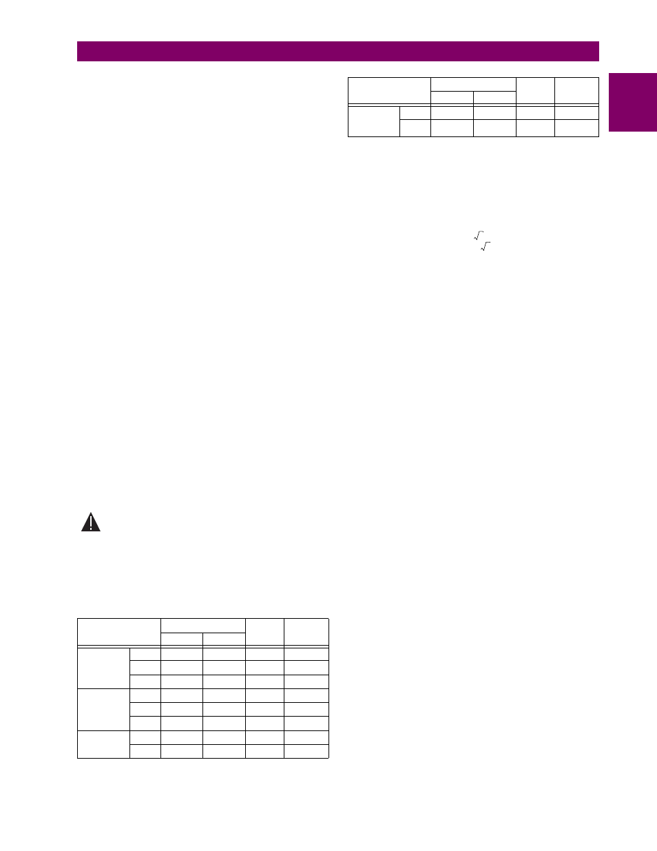
VOLTAGE
MAKE/CARRY
BREAK
MAX.
LOAD
CTS
0.2 s
DC
RESISTIVE
30 V
10 A
30 A
10 A
300 W
125 V
10 A
30 A
0.5 A
62.5 W
250 V
10 A
30 A
0.3 A
75 W
DC
INDUCTIVE
L/R = 40 ms
30 V
10 A
30 A
5 A
150 W
125 V
10 A
30 A
0.25 A
31.3 W
250 V
10 A
30 A
0.15 A
37.5 W
AC
RESISTIVE
120 V
10 A
30 A
10 A
2770 VA
250 V
10 A
30 A
10 A
2770 VA
WARNING
AC
INDUCTIVE
PF = 0.4
120 V
10 A
30 A
4 A
480 VA
250 V
10 A
30 A
3 A
750 VA
VOLTAGE
MAKE/CARRY
BREAK
MAX.
LOAD
CTS
0.2 s
3
3