Table 6–2: data formats (sheet 2 of 5) – GE 489 User Manual
Page 197
GE Multilin
489 Generator Management Relay
6-35
6 COMMUNICATIONS
6.3 MODBUS MEMORY MAP
6
F107
Unsigned
16 bit integer
Nominal frequency selection
0 = -----, 1 = 60 Hz, 2 = 50 Hz, 3 = 25 Hz
F109
Unsigned
16 bit integer
Breaker status switch type
0 = Auxiliary a, 1 = Auxiliary b
F115
Unsigned
16 bit integer
Alarm / trip type selection
0 = Off, 1 = Latched, 2 = Unlatched
F117
Unsigned
16 bit integer
Reset mode
0 = All Resets, 1 = Remote Reset Only
F118
Unsigned
16 bit integer
Setpoint Group
0 = Group 1, 1 = Group 2
F120
Unsigned
16 bit integer
RTD type
0 = 100 Ohm Platinum, 1 = 120 Ohm Nickel, 2 = 100 Ohm Nickel, 3 = 10 Ohm Copper
F121
Unsigned
16 bit integer
RTD application
0 = None, 1 = Stator, 2 = Bearing, 3 = Ambient, 4 = Other
F122
Unsigned
16 bit integer
RTD voting selection
1 = RTD #1, 2 = RTD #2, 3= RTD #3,..., 12 = RTD #12
F123
Unsigned
16 bit integer
Alarm / trip status
0 = Not Enabled, 1 = Inactive, 2 = Timing Out, 3 = Active Trip, 4 = Latched Trip
F124
Unsigned
16 bit integer
Phase rotation selection
0 = ----, 1 = ABC, 2 = ACB
F126
Unsigned
16 bit integer
Disabled / Enabled selection
0 = Disabled, 1 = Enabled
F127
Unsigned
16 bit integer
Analog output parameter selection
F128
Unsigned
16 bit integer
Overcurrent curve style selection
F129
Unsigned
16 bit integer
Analog input selection
0 = Disabled, 1 = 4-20 mA, 2 = 0-20 mA, 3 = 0-1 mA
F130
Unsigned
16 bit integer
Pickup type
0 = Over, 1 = Under
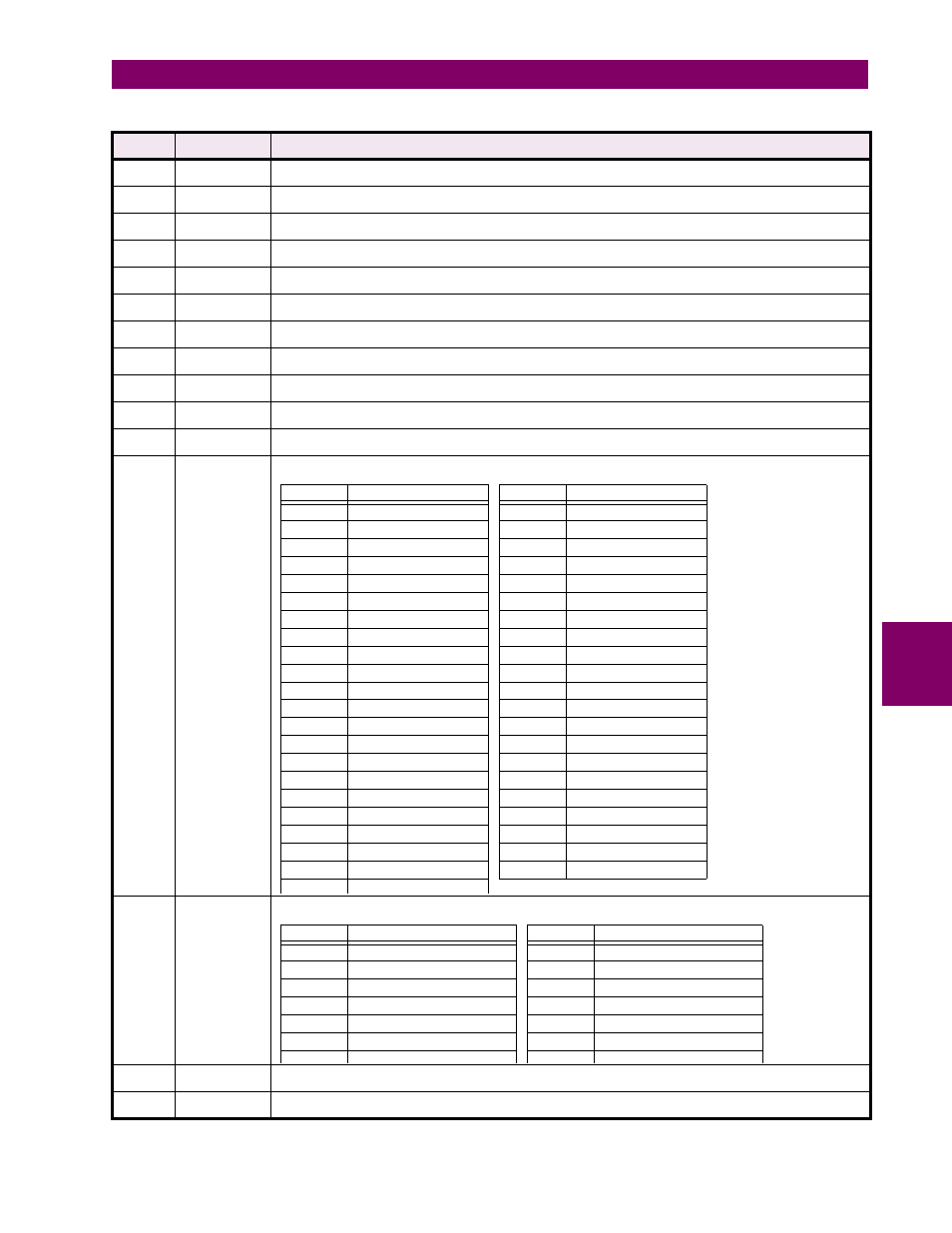
Table 6–2: DATA FORMATS (SHEET 2 OF 5)
FORMAT
CODE
TYPE
DEFINITION
VALUE
PARAMETER
VALUE
PARAMETER
0
None
22
AB Voltage
1
IA Output Current
23
BC Voltage
2
IB Output Current
24
CA Voltage
3
IC Output Current
25
Average Voltage
4
Avg. Output Current
26
Volts / Hertz
5
Neg. Seq. Current
27
Frequency
6
Averaged Gen. Load
28
Neutral Voltage (3rd)
7
Hottest Stator RTD
29
Power Factor
8
Hottest Bearing RTD
30
Reactive Power (Mvar)
9
Ambient RTD
31
Real Power (MW)
10
RTD #1
32
Apparent Power (MVA)
11
RTD #2
33
Analog Input 1
12
RTD #3
34
Analog Input 2
13
RTD #4
35
Analog Input 3
14
RTD #5
36
Analog Input 4
15
RTD #6
37
Tachometer
16
RTD #7
38
Therm. Capacity Used
17
RTD #8
39
Current Demand
18
RTD #9
40
Mar Demand
19
RTD #10
41
MW Demand
20
RTD #11
42
MVD Demand
21
RTD #12
VALUE
PARAMETER
VALUE
PARAMETER
0
ANSI Extremely Inverse
7
IEC Short Inverse
1
ANSI Very Inverse
8
IAC Extremely Inverse
2
ANSI Normally Inverse
9
IAC Very Inverse
3
ANSI Moderately Inverse
10
IAC Inverse
4
IEC Curve A (BS142)
11
IAC Short Inverse
5
IEC Curve B (BS142)
12
Flexcurve™
6
IEC Curve C (BS142)
13
Definite Time