Pmc connectors and pinouts (j11 through j14), J11 connector and pinout – FANUC Robotics America V7865* User Manual
Page 84
84
A
V7865 Product Manual
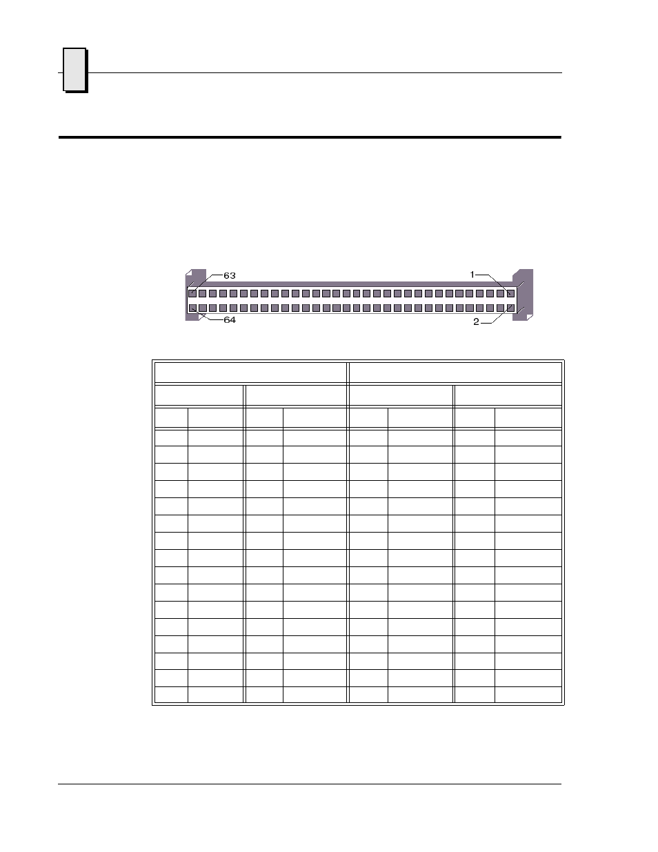
PMC Connectors and Pinouts (J11 through J14)
The PCI Mezzanine Card (PMC) carries the same signals as the PCI standard;
however, the PMC standard uses a completely different form factor. Tables A-4
through A-7 are the pinouts for the PMC connectors (J11, J12, J13 and J14).
J11 Connector and Pinout
Table A-4 PMC Connector Pinout (J11)
PMC Connector (J11)
PMC Connector (J11)
Left Side
Right Side
Left Side
Right Side
Pin
Name
Pin
Name
Pin
Name
Pin
Name
1
GND
2
-12
33
FRAME#
34
GND
3
GND
4
INTA#
35
GND
36
IRDY#
5
INTB#
6
INTC#
37
DEVSEL#
38
+5 V
7
BMODE1
8
+5 V
39
PCIXCAP
40
LOCK#
9
INTD#
10
NC
41
SDONE#
42
+3.3V
11
GND
12
NC
43
PAR
44
GND
13
CLK
14
GND
45
+3.3V
46
AD[15]
15
GND
16
GNT#
47
AD[12]
48
AD[11]
17
REQ#
18
+5 V
49
AD[9]
50
+5 V
19
+3.3V
20
AD[31]
51
GND
52
C/BE[0]#
21
AD[28]
22
AD[27]
53
AD[6]
54
AD[5]
23
AD[25]
24
GND
55
AD[4]
56
GND
25
GND
26
C/BE[3]#
57
+3.3V
58
AD[3]
27
AD[22]
28
AD[21]
59
AD[2]
60
AD[1]
29
AD[19]
30
+5 V
61
AD[0]
62
+5 V
31
+3.3V
32
AD[17]
63
GND
64
REQ64#