Connector locations, Figure a-1 – FANUC Robotics America V7865* User Manual
Page 74
74
A
V7865 Product Manual
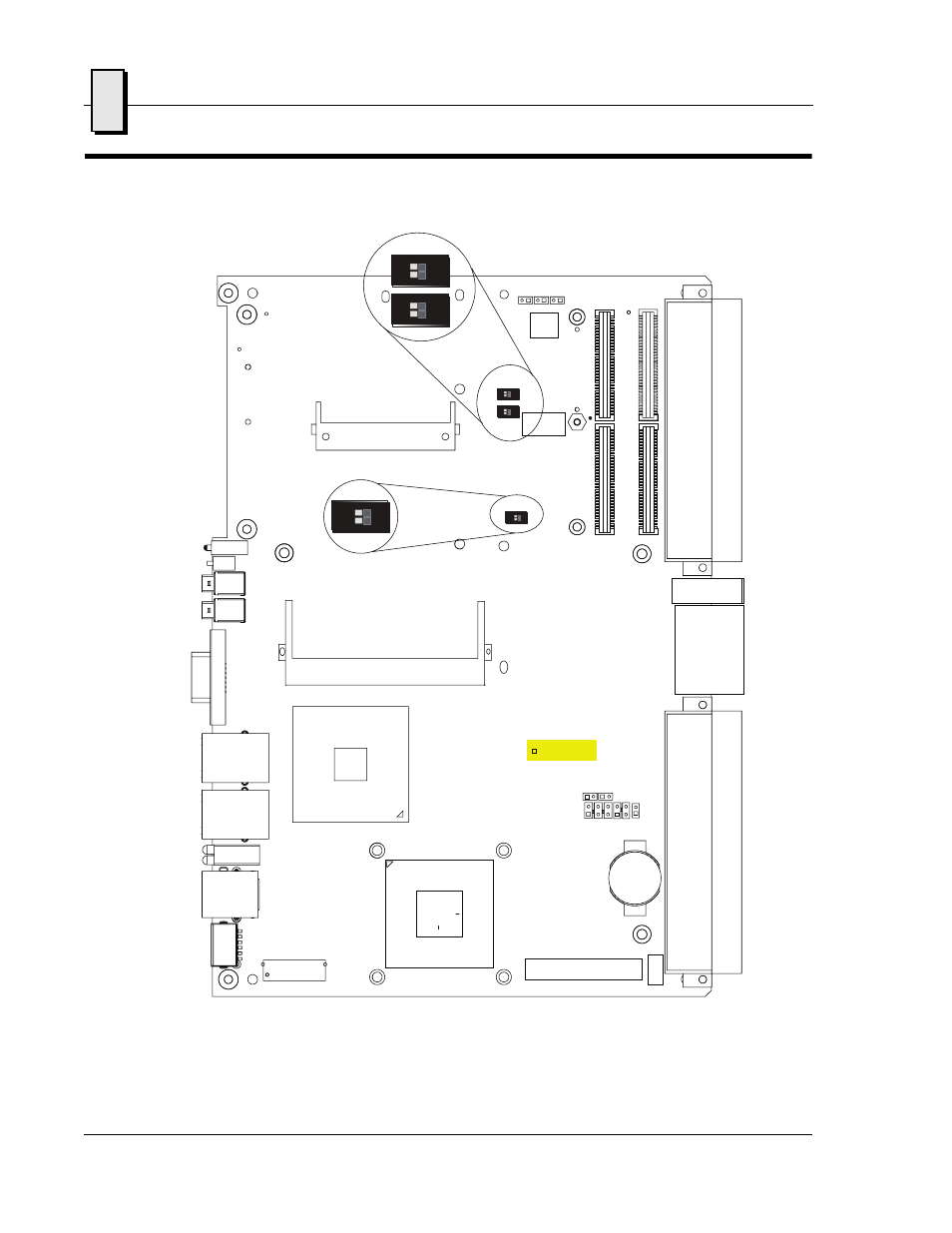
Connector Locations
Figure A-1 Connector Locations
CompactFlash
SVGA
GbE
GbE
USB
COM1
M/K
USB
Reset
Status LEDs
Optional
P0
Vita 41.3
S1
J30
J29
J28
J33
J32
J35
J36
J21
P2
P1
J11
J12
J1
3
J14
P7
S3
S6
S7
P8
E14
E13
E17
E27
E15
G1*
* The G1 keying pin is provided with the Vita 41.3 P0 option.
E20 E11 E12
E10
E9
E19
1 3 5 1 3
P7
SODIMM
INDICATES PIN 1
ON
1 2
ON
1 2
ON
1 2
ON
1 2
ON
1 2
ON
1 2