Timer 4 load count register (tmrlcr4), Timer 1 & 2 current count register (tmrccr12), Timer 3 current count register (tmrccr3) – FANUC Robotics America V7865* User Manual
Page 64
64
3
V7865 Product Manual
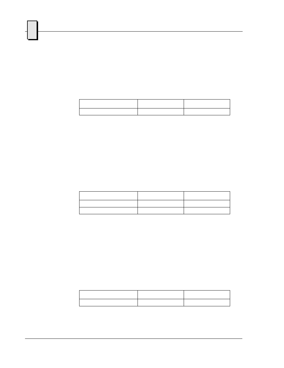
Timer 4 Load Count Register (TMRLCR4)
Timer 4 is 32-bits wide and obtains its load count from the Timer 4 Load Count
Register (TMRLCR4), located at offset 0x18 from the address in BAR2. The mapping
of bits in this register are as follows:
When this field is written, Timer 4 is loaded with the written value on the next rising
edge of the timer clock, regardless of whether the timer is enabled or disabled. The
value stored in this register is also automatically reloaded on terminal count (or
timeout) of the timer.
Timer 1 & 2 Current Count Register (TMRCCR12)
The current count of timers 1 & 2 may be read via the Timer 1 & 2 Current Count
Register (TMRCCR12), located at offset 0x20 from the address in BAR2. The mapping
of bits in this register are as follows:
When either field is read, the current count value is latched and returned. There are
two modes that determine how the count is latched depending on the setting of the
“Read Latch Select” bit in the WDT Control Status Register (CSR2). See the CSR2
register description for more information on these two modes.
Timer 3 Current Count Register (TMRCCR3)
The current count of Timer 3 may be read via the Timer 3 Current Count Register
(TMRCCR3), located at offset 0x24 from the address in BAR2. The mapping of bits in
this register are as follows:
Field
Bits
Read or Write
Timer 4 Load Count
TMRLCR4[31..0]
Read/Write
Field
Bits
Read or Write
Timer 2 Count
TMRCCR12[31..16]
Read Only
Timer 1 Count
TMRCCR12[15..0]
Read Only
Field
Bits
Read or Write
Timer 3 Count
TMRCCR3[31..0]
Read Only