Pci interrupts – FANUC Robotics America V7865* User Manual
Page 49
49
Interrupts
2
PCI Interrupts
The Tsi148 VME Bridge and the PMC site of the V7865 connect Standard PCI Interrupt
Lines to the PCI-E to PCI-X bridge as shown in Figure 2-1 on page 51. The PCI-E
bridges (PLX PEX8114) convert the PCI INTx interrupts into virtual PCI Express INTA
interrupts that are signaled back to the chipset over the PCI Express Interface.
Interrupts on Peripheral Component Interconnect (PCI) Local Bus are optional and
defined as “level sensitive,” asserted low (negative true), using open drain output
drivers. The assertion and de-assertion of an interrupt line, INTx#, is asynchronous to
CLK. A device asserts its INTx# line when requesting attention from its device driver.
Once the INTx# signal is asserted, it remains asserted until the device driver clears the
pending request. When the request is cleared, the device de-asserts its INTx# signal.
PCI defines one interrupt line for a single function device and up to four interrupt
lines for a multifunction device or connector. For a single function device, only INTA#
may be used while the other three interrupt lines have no meaning. Figure 2-1 on
page 51 depicts the V7865 interrupt logic pertaining to timer NVRAM operations and
the PCI expansion site.
Any function on a multifunction device can be connected to any of the INTx# lines.
The Interrupt Pin register defines which INTx# line the function uses to request an
interrupt. If a device implements a single INTx# line, it is called INTA#; if it
implements two lines, they are called INTA# and INTB#; and so forth. For a
multifunction device, all functions may use the same INTx# line, or each may have its
own (up to a maximum of four functions), or any combination thereof. A single
function can never generate an interrupt request on more than one INTx# line.
The slave PIC accepts the PCI interrupts through lines that are defined by the BIOS.
The BIOS defines which interrupt line to utilize depending on which system requires
the use of the line.
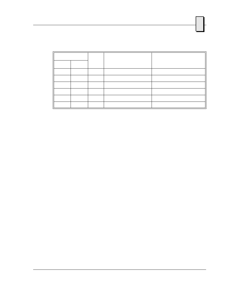
75
117
IRQ13
Math Coprocessor
76
118
IRQ14
AT Hard Drive
77
119
IRQ15
Flash Drive
78-7F
120-127
Reserved by DOS
Same as Real Mode
80-F0
128-240
Reserved for BASIC
Same as Real Mode
F1-FF
241-255
Reserved by DOS
Same as Real Mode
Table 2-4 Interrupt Vector Table (Continued)
Interrupt No.
IRQ
Line
Real Mode
Protected Mode
HEX
DEC