Timers, General, Timer control status register 1 (tcsr1) – FANUC Robotics America V7865* User Manual
Page 61
61
Timers
3
Timers
General
The V7865 provides four user-programmable timers (two 16-bit and two 32-bit) which
are completely dedicated to user applications and are not required for any standard
system function. Each timer is clocked by independent generators with selectable
rates of 2MHz, 1MHz, 500kHz and 250kHz. Each timer may be independently
enabled and each is capable of generating a system interrupt on timeout.
Events can be timed by either polling the timers or enabling the interrupt capability of
the timer. A status register allows for application software to determine which timer
is the cause of any interrupt.
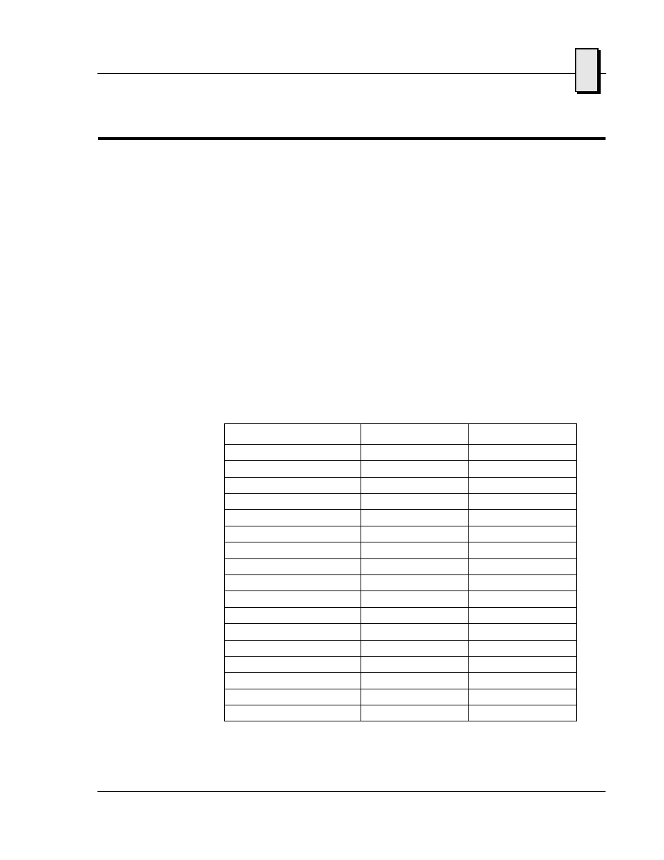
Timer Control Status Register 1 (TCSR1)
The timers are controlled and monitored via the Timer Control Status Register 1
(TCSR1) located at offset 0x00 from the address in BAR2. The mapping of the bits in
this register are as follows:
Field
Bits
Read or Write
Timer 1 Caused IRQ
TCSR1[0]
R/W
Timer 1 Enable
TCSR1[1]
R/W
Timer 1 IRQ Enable
TCSR1[2]
R/W
Timer 1 Clock Select
TCSR1[4..3]
R/W
Timer 2 Caused IRQ
TCSR1[8]
R/W
Timer 2 Enable
TCSR1[9]
R/W
Timer 2 IRQ Enable
TCSR1[10]
R/W
Timer 2 Clock Select
TCSR1[12..11]
R/W
Timer 3 Caused IRQ
TCSR1[16]
R/W
Timer 3 Enable
TCSR1[17]
R/W
Timer 3 IRQ Enable
TCSR1[18]
R/W
Timer 3 Clock Select
TCSR1[20..19]
R/W
Timer 4 Caused IRQ
TCSR1[24]
R/W
Timer 4 Enable
TCSR1[25]
R/W
Timer 4 IRQ Enable
TCSR1[26]
R/W
Timer 4 Clock Select
TCSR1[28..27]
R/W
Reserved
All Other Bits
R/W
All of these bits default to “0” after system reset.