Figure b.2 connection of the main unit and cvcf, Table b.1 signal line definitions, Definitions – FUJITSU PRIMEQUEST 1000 Series C122-E119EN User Manual
Page 104
B.3
Connection of Main Unit and CVCF and Signal Line Definitions
This section shows the connection of the main unit and CVCF. This section also provides definitions of the signal
lines.
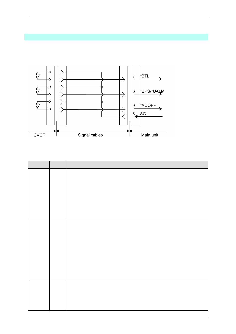
The figure below is a connection diagram of the main unit and CVCF.
FIGURE B.2 Connection of the main unit and CVCF
TABLE B.1 Signal line definitions
Signal name
Pin
Function
*BPS/
*UALM
6
Hardware abnormality signal
When this signal becomes valid, the PRIMEQUEST notifies the system administrator of
a CVCF abnormal condition.
When the *ACOFF signal goes ON with the *BPS signal already ON, the system judges
that battery-supported operation cannot be executed by the CVCF. In this case, forcible
system stop is executed instead of shutdown processing. Stopping operation in this manner
may cause damage to the system or data.
The signal becomes valid when this line and GND (pin 5) are short-circuited.
*BTL
7
Near-end-of-battery-discharge notification signal
The signal on this line notifies the PRIMEQUEST of the approaching end of discharge of
the CVCF battery.
This signal is used to notify the PRIMEQUEST that the power supply will shortly be
stopped because of battery power depletion, when power is being supplied from the CVCF
due to a power failure.
When the signal goes ON, the system judges that battery-supported operation cannot be
executed any longer. In this case, forcible system stop is executed instead of shutdown
processing. Stopping operation in this manner may cause damage to the system or data.
The signal becomes valid when this line and GND (pin 5) are short-circuited.
*ACOFF
9
Power failure detection signal
The signal on this line notifies the PRIMEQUEST that the CVCF has detected a power
failure.
When the signal becomes valid, the PRIMEQUEST performs automatic shutdown
processing.
PRIMEQUEST 1000 Series Hardware Installation Manual
APPENDIX B UPC Interface
84
C122-H004-07EN