1 gpio card pinouts, Figure 5-3: gpio cable for ivce-c608 and ivce-c604, Figure 5-4: gpio card pinouts – IEI Integration IVCME-C604 User Manual
Page 46
IVCE-C608/IVCE-C604/IVCME-C604 Capture Card
Page 18
Figure 5-3: GPIO Cable for IVCE-C608 and IVCE-C604
Step 3:
Push the cable connector onto the video capture card GPIO connector making
sure the pins are correctly aligned.
Step 4:
Next, connect the GPIO cable connector to the GPIO connector on the GPIO
card (CN6).
Step 0:
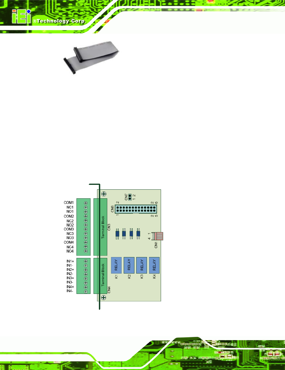
5.4.4.1 GPIO Card Pinouts
The following diagram shows the pinouts of the two terminal blocks of the optional GPIO
card.
Figure 5-4: GPIO Card Pinouts