4 ivce-c604 reset input connector (cn4), 5 ivce-c604 reset output connector (cn5), Table 4-7: ivce-c604 reset input connector pinouts – IEI Integration IVCME-C604 User Manual
Page 36
IVCE-C608/IVCE-C604/IVCME-C604 Capture Card
Page 8
Green:
self-defined
Red:
self-defined
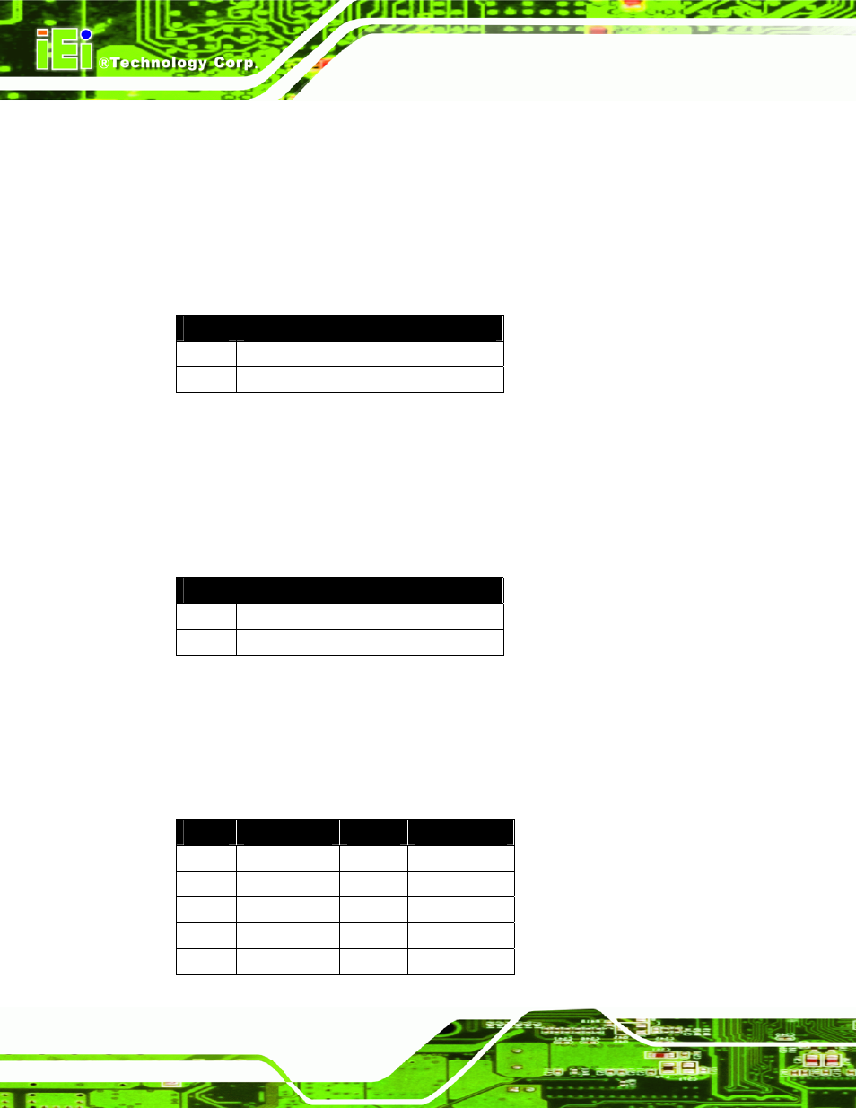
4.1.2.4 IVCE-C604 Reset Input Connector (CN4)
Use the reset input connector (CN4) to connect to the reset button of the system chassis
to enable the multiple card cascade reset function. Pinouts for the connector are shown in
Pin No.
Signal
1 Reset
input
2 GND
Table 4-7: IVCE-C604 Reset Input Connector Pinouts
4.1.2.5 IVCE-C604 Reset Output Connector (CN5)
Use the reset output connector (CN5) to connect to the reset connector on the
motherboard to enable the multiple card cascade reset function. Pinouts for the connector
are shown in Table 4-8.
Pin No.
Signal
1 Reset
output
2 GND
Table 4-8: IVCE-C604 Reset Output Connector Pinouts
4.1.2.6 IVCE-C604 Video/Audio Input/Output Connector (J1)
Compatible cameras connect to the IVCE-C604 through the DB-26 female connector (via
the D-SUB to BNC and RCA cable). Pinouts for the connector are shown in Table 4-9.
Pin No.
Signal
Pin No.
Signal
1
Video In CH1
2
Video In CH2
3
Video In CH3
4
Video In CH4
5 NC
6 NC
7 NC
8 NC
9
Video Output 1
10
NC