2 ivce-c604 pinouts, Table 4-6: ivce-c604 connectors – IEI Integration IVCME-C604 User Manual
Page 34
IVCE-C608/IVCE-C604/IVCME-C604 Capture Card
Page 6
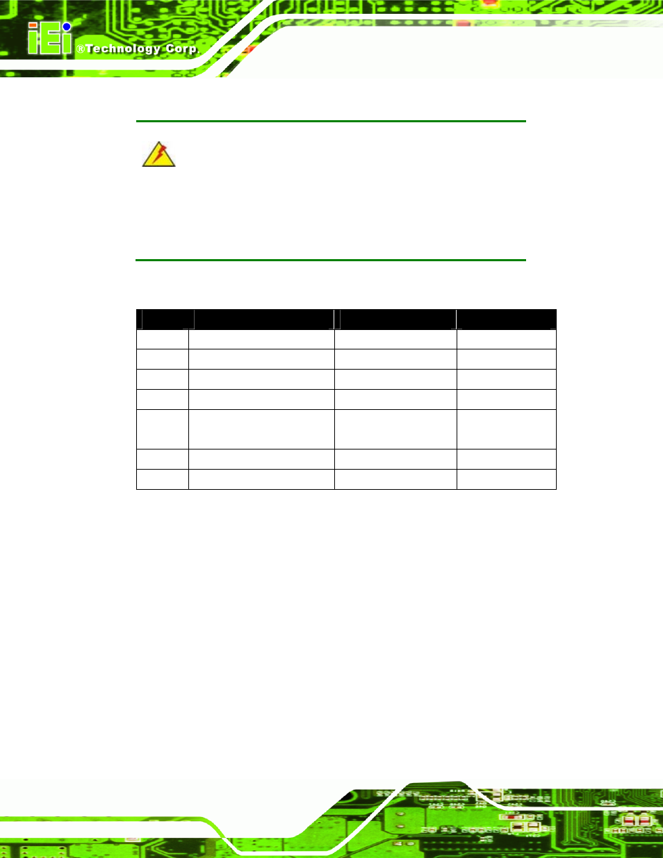
4.1.2 IVCE-C604 Pinouts
WARNING:
The other connectors, jumpers and interfaces on the board not
specified below are for R&D diagnostic purposes and should not be
used by the end user.
The IVCE-C604 has the following connectors and interfaces on board:
Quantity
Connector Name
Connector Type
Labels
1
Rotary Switch (ID Selection)
16-position switch
SW1
1
LED screen
LED screen
LED2
1
LED indicators
Red, amber, green LED
LED1
1
GPIO connectors
26-pin box header
CN3
1 Video/Audio
input/output
connector
DB-26 female
J1
1
Reset input connector
2-pin header
CN4
1
Reset output connector
2-pin header
CN5
Table 4-6: IVCE-C604 Connectors
Figure 4-2 shows the connectors and interfaces on the IVCE-C604.