1 ivce-c608 switch (sw1), 2 ivce-c608 led screen (led2), 3 ivce-c608 led indicators (led1) – IEI Integration IVCME-C604 User Manual
Page 31
IVCE-C608/IVCE-C604/IVCME-C604 Capture Card
Page 3
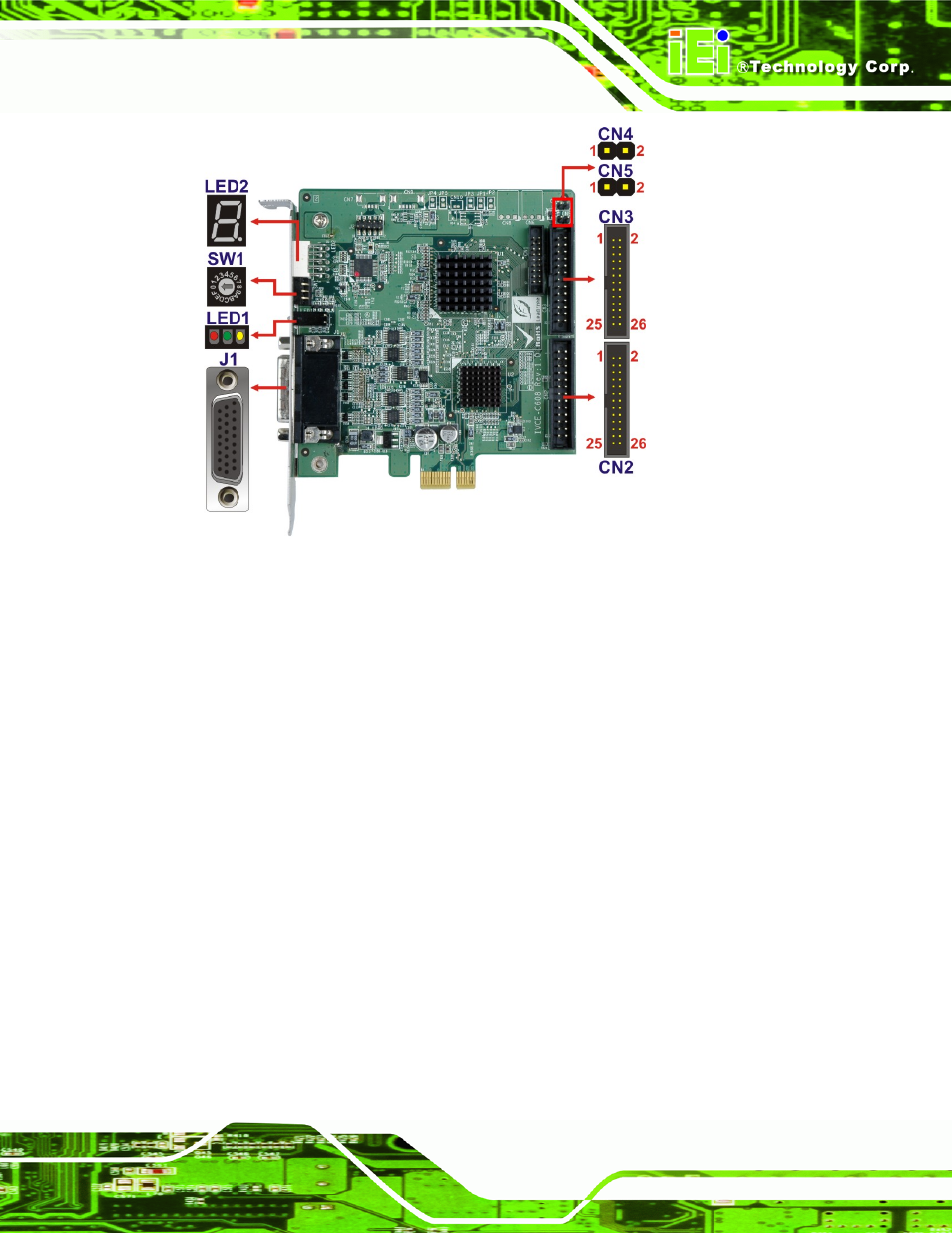
Figure 4-1: IVCE-C608 Connectors and Pinouts (pin numbers in red)
4.1.1.1 IVCE-C608 Switch (SW1)
Use the 16-position rotary switch (SW1) to set the ID for the board. Up to 16 IVCE-C608
can be installed in a single system. Each card must be allocated a unique ID. Switch ID
settings are explained in more detail in Section 5.4.5.
4.1.1.2 IVCE-C608 LED Screen (LED2)
The LED screen shows the ID number of the IVCE-C608. Sixteen IVCE-C608 cards can
be connected together in a singles system. Each card has a unique ID setting as specified
by the unique rotary switch (SW1) setting described above and in Section 5.4.5. The
unique card ID specified by the rotary switch (SW1) is specified on the screen.
4.1.1.3 IVCE-C608 LED Indicators (LED1)
The LED indicator (LED1) includes three LED indicators: Amber, green and red. These
LED indicators show the system status as described below:
Amber: watchdog alarm